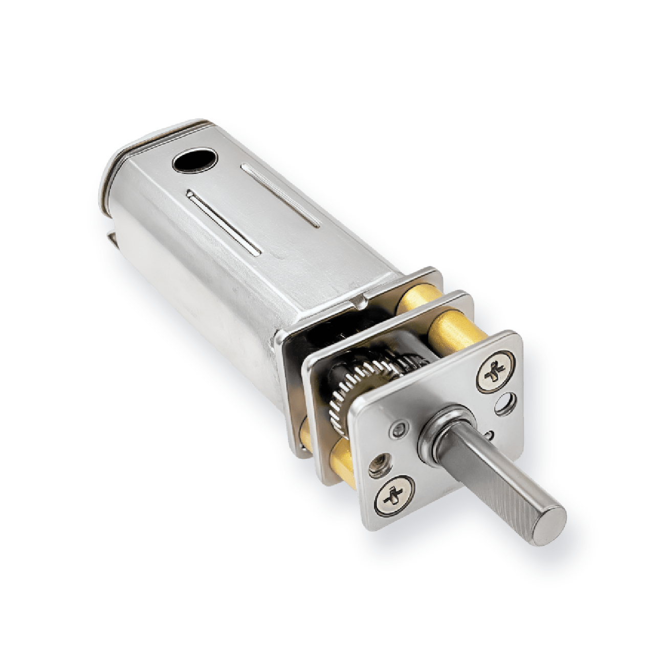
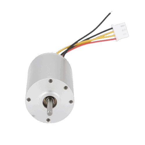
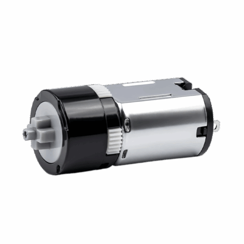


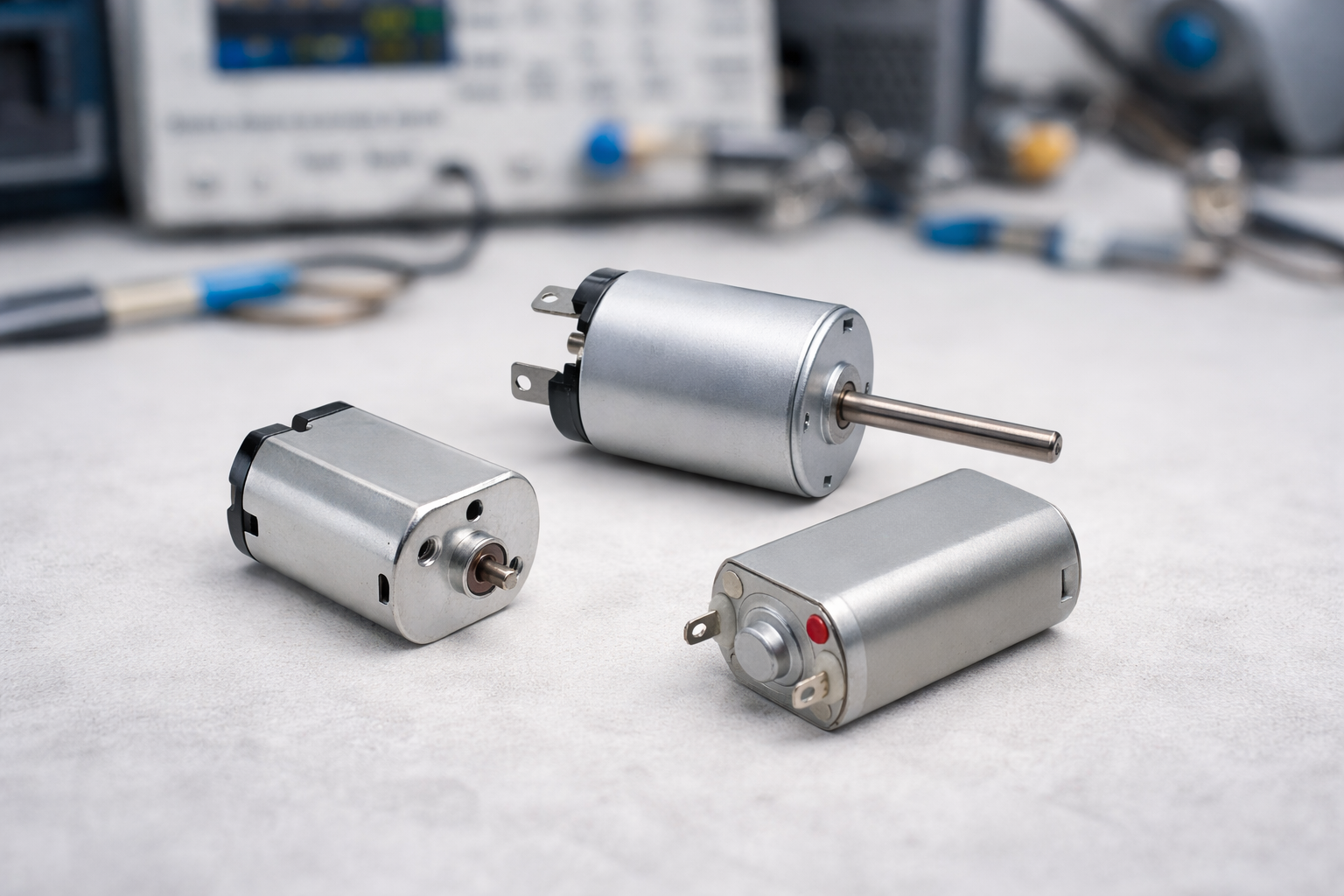
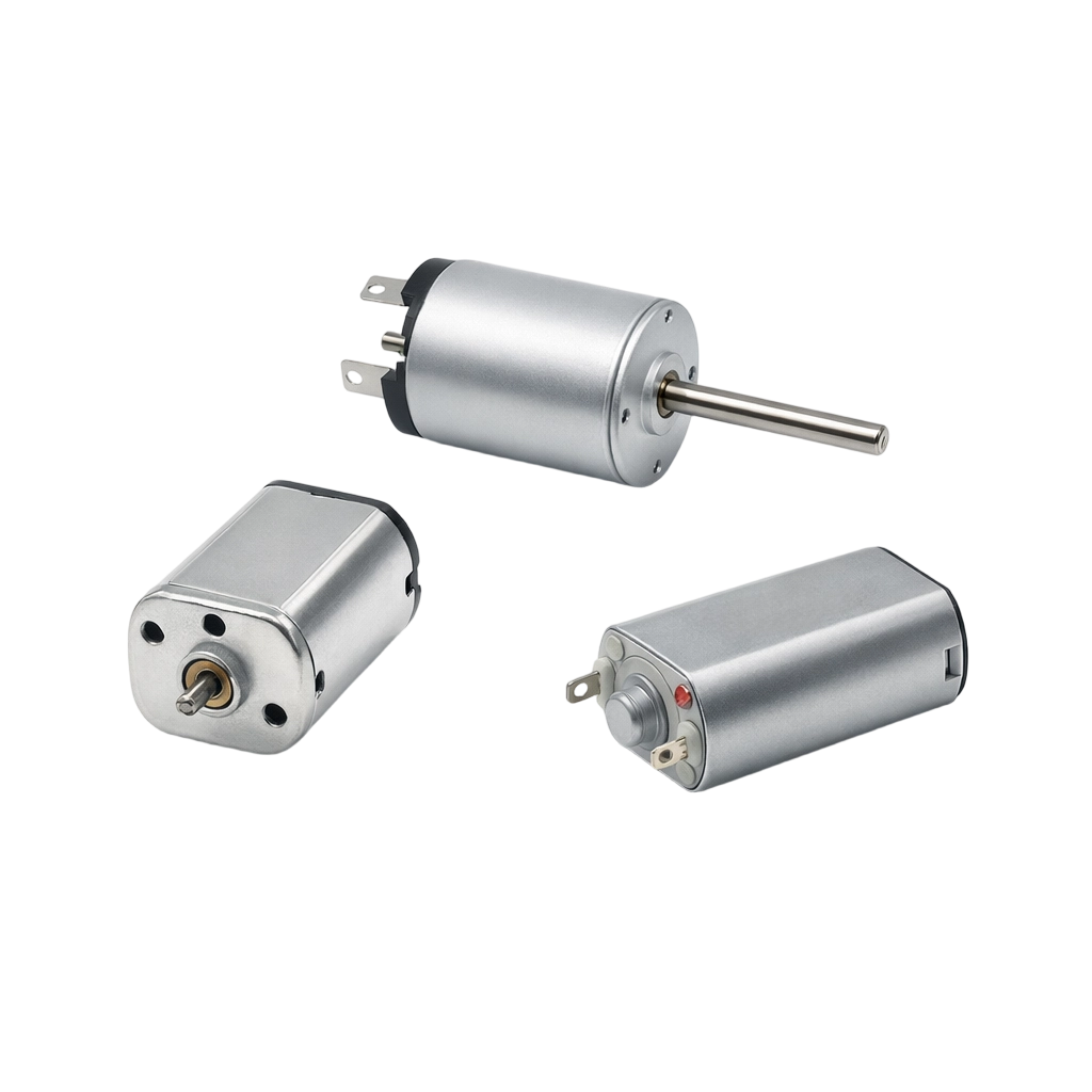
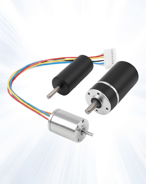
20mm Diameter 180 Micro Brushed DC Motor
This 180 micro brushed DC motor delivers a larger torque envelope than 030/N20 classes, designed for compact drives that need stronger push capability and stable output under load.


This 180 micro brushed DC motor delivers a larger torque envelope than 030/N20 classes, designed for compact drives that need stronger push capability and stable output under load.


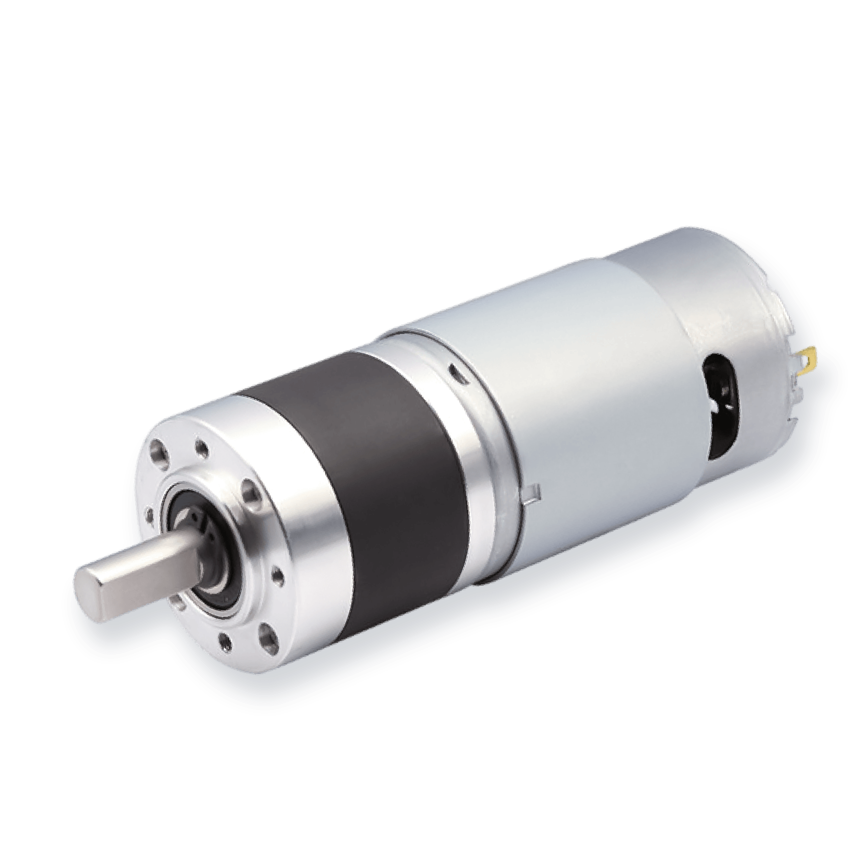
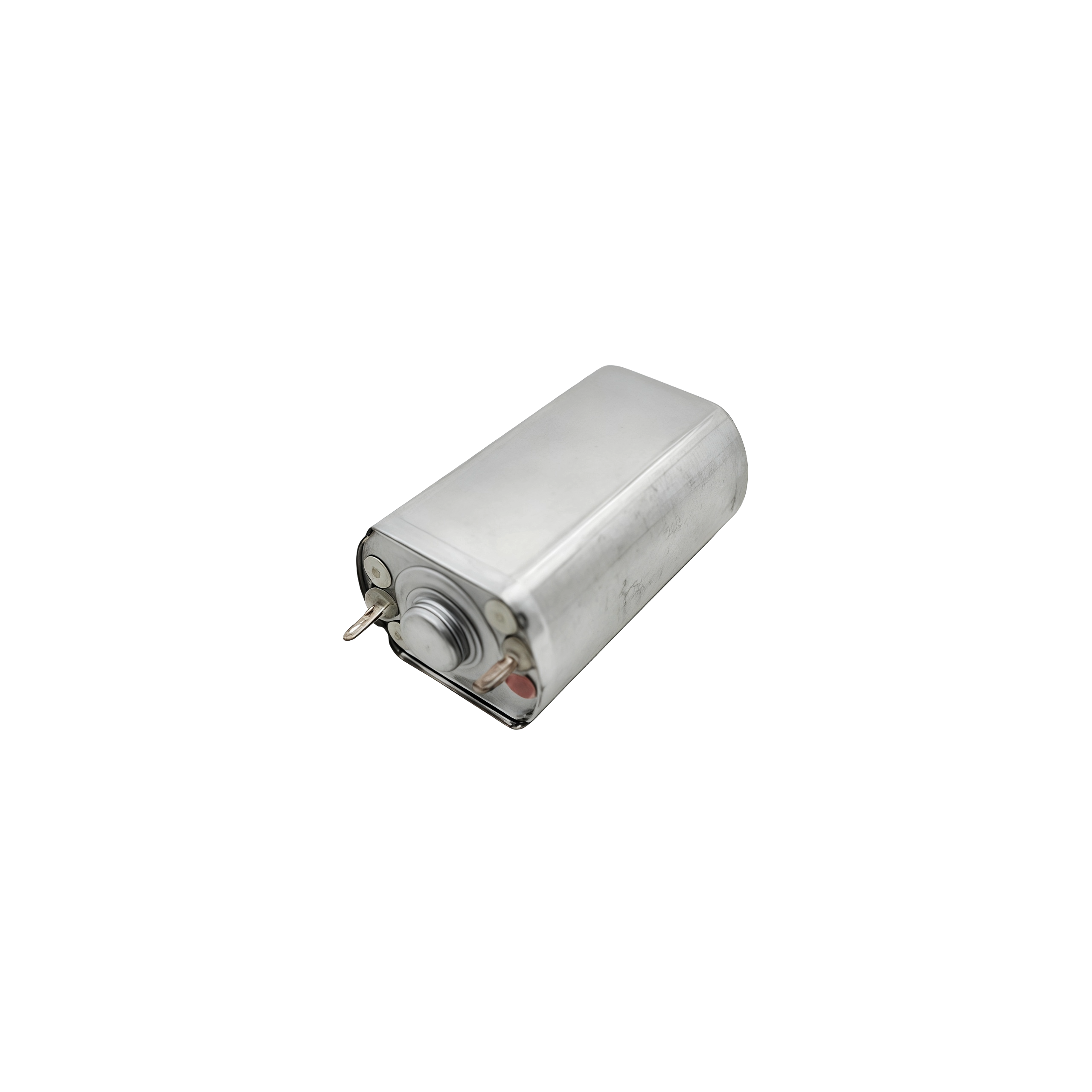
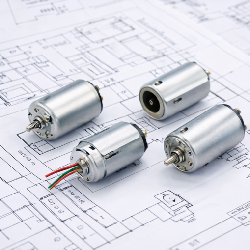
This model is positioned as a higher-torque micro brushed motor, suitable when smaller formats cannot provide enough force margin and you need clear efficiency and output reference points.
| Model | Voltage (V) | No Load | Max Efficiency | Max Output | Stall | ||||||
| Current (A) | Speed (rpm) | Current (A) | Speed (rpm) | Torque (g.cm) | Current (A) | Speed (rpm) | Torque (g.cm) | Current (A) | Torque (g.cm) | ||
| SLW-FF180-17140 | 6 | 0.074 | 7074 | 0.358 | 5869 | 22.5 | 0.909 | 3537 | 65.9 | 1.744 | 131.8 |
| SLW-FF180-11310 | 24 | 0.047 | 11562 | 0.252 | 9759 | 36.7 | 0.706 | 5781 | 117.8 | 1.365 | 235.6 |
For additional customization or reference configurations, please feel free to contact us.


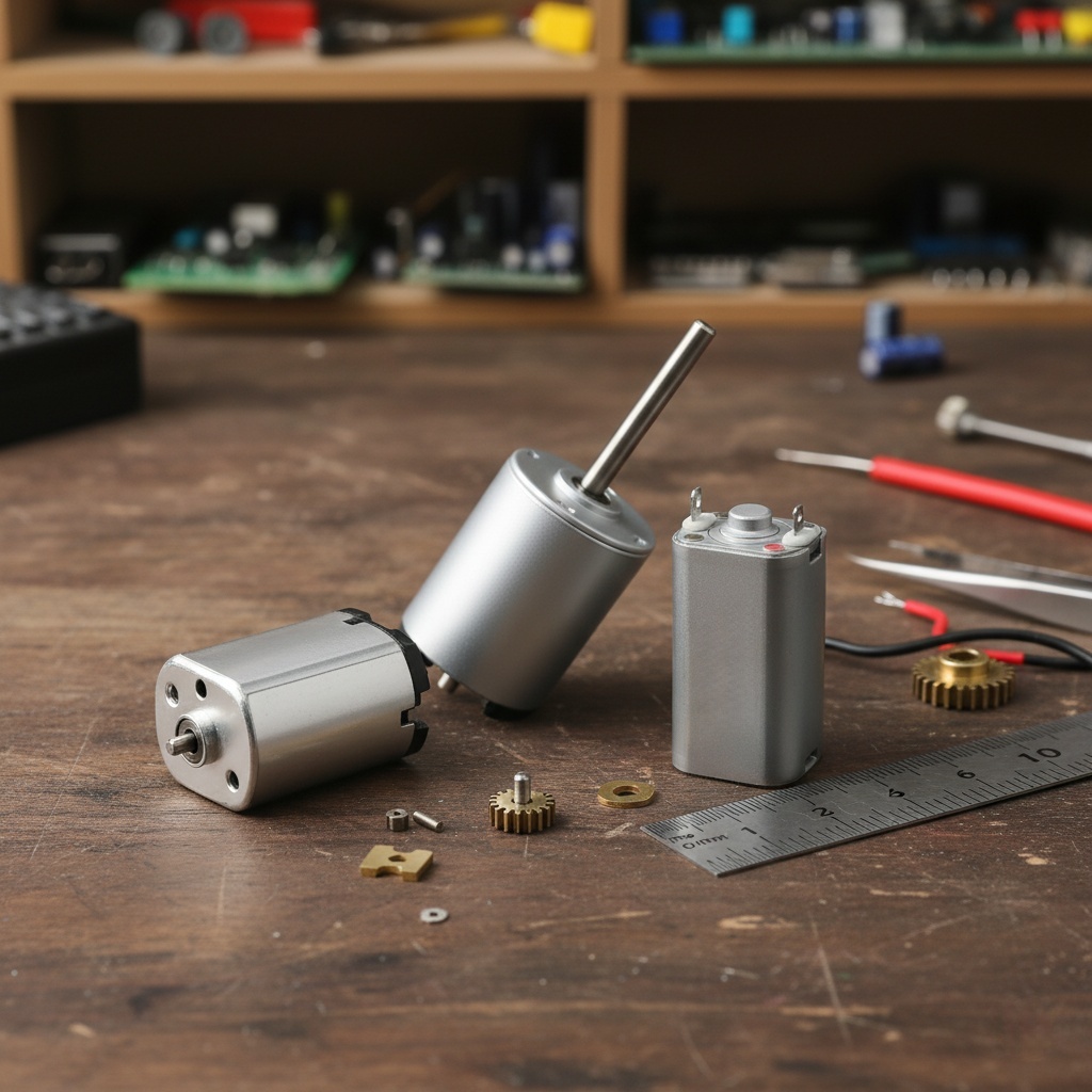
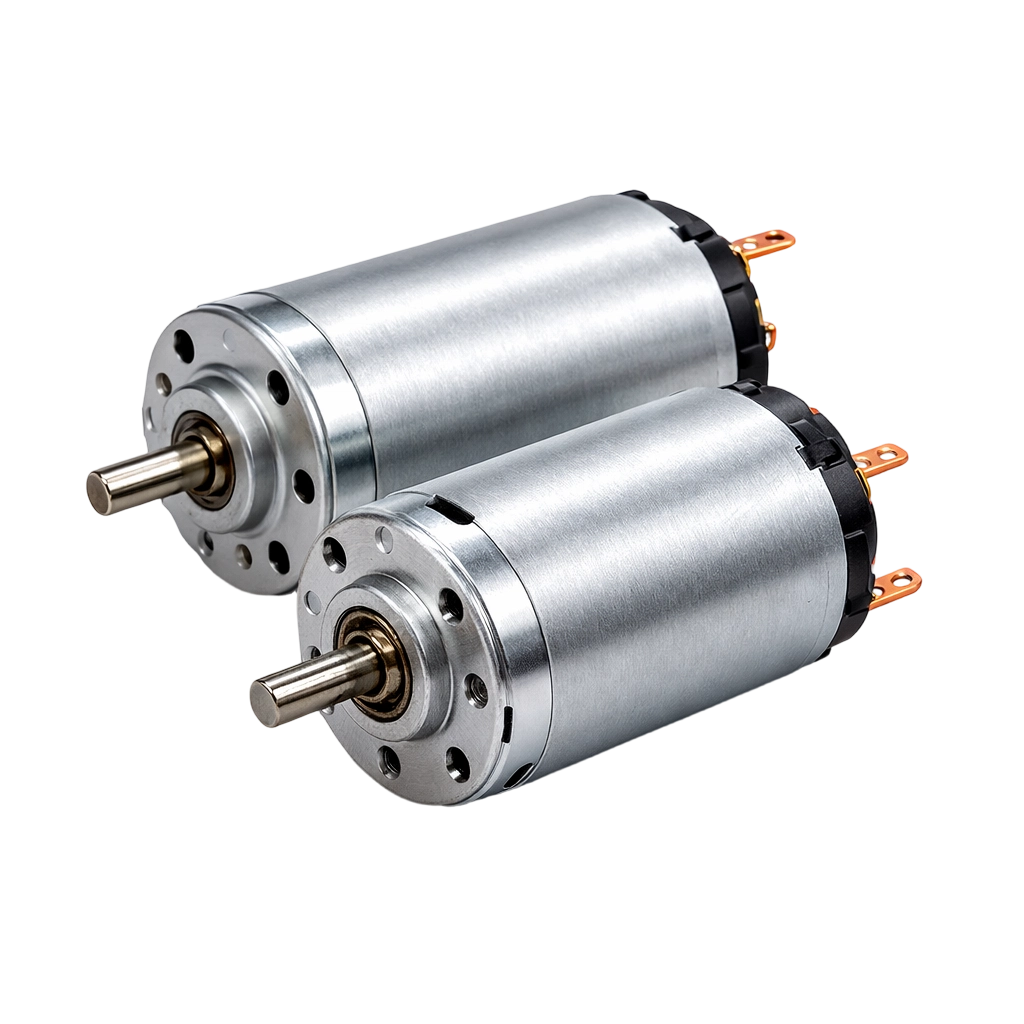
Compared with N20/030 classes, the 180 format is positioned for higher torque demand where friction, load mass, or intermittent resistance is higher.
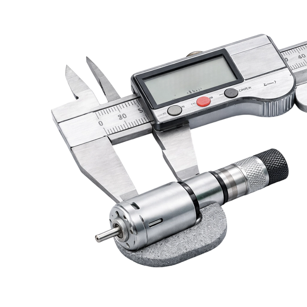
Max-efficiency and max-output points give you two realistic sizing references: one for continuous running stability and one for short burst capability.
Stall current defines the electrical worst case. This is critical when your product uses small drivers, thin harnesses, or battery packs with voltage sag.
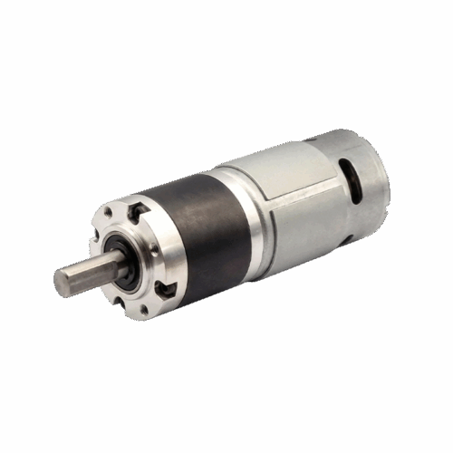
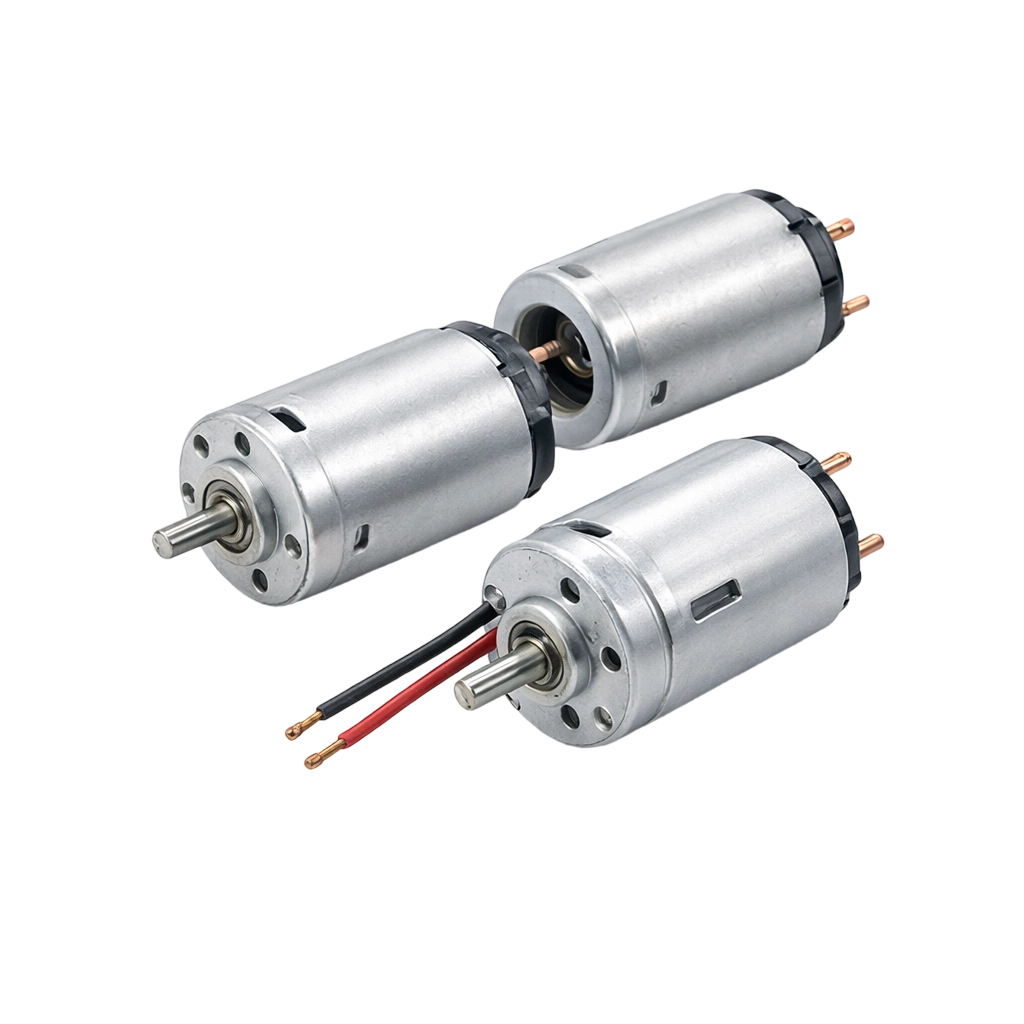
The two model options allow tiered product design where the mechanical footprint can remain similar while performance changes.

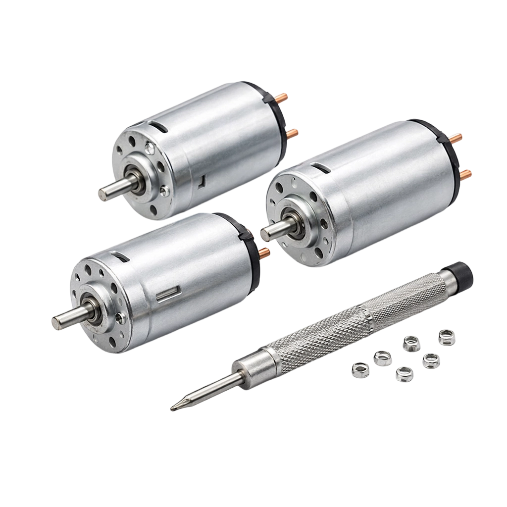


If you share your available space and the driven load type, we can help narrow the most suitable configuration quickly.

English

Japanese

Korean
Tell us about your project or application, and our team will get back to you with technical support, product recommendations, or a customized motor solution.