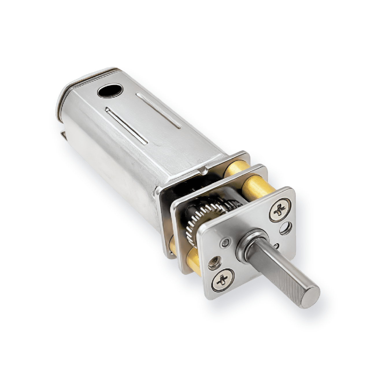
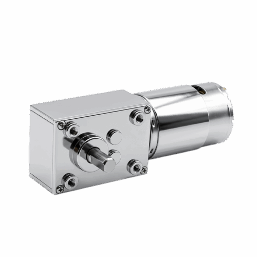
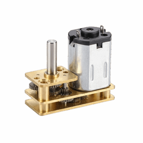
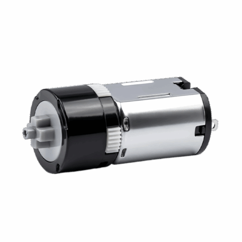


12mm Spur Gearbox & Reducer
This 12mm spur gearbox is designed for compact drive systems that need a wider ratio span and higher torque margin, with a customizable output shaft to simplify integration across different mechanisms.


This 12mm spur gearbox is designed for compact drive systems that need a wider ratio span and higher torque margin, with a customizable output shaft to simplify integration across different mechanisms.


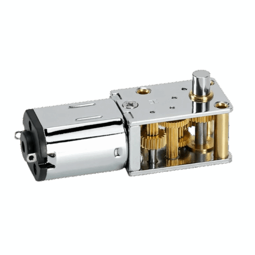
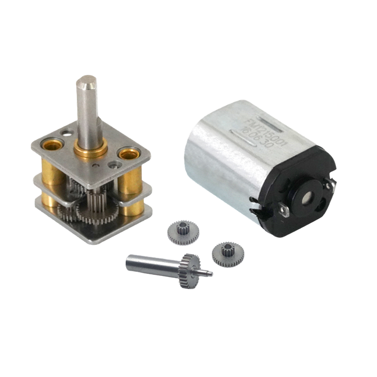
This spur gearbox uses a gear-hobbing structure to support broad reduction choices while keeping a clean, compact mounting package.
| Index | Gear Ratio | Actual Ratio | Stages | Overall Size | Output Direction | Motor Gear Teeth | Motor Gear ID (mm) | Rated Torque (g·cm) | Allowable Peak Torque (g·cm) |
| 1 | 3 | 3.121 | 2 | 12*10*9 | Same | 18 | 1 | 200 | 600 |
| 2 | 5 | 5.067 | 2 | 12*10*9 | Same | 13 | 1 | 200 | 600 |
| 3 | 10 | 9.677 | 2 | 12*10*9 | Same | 13 | 1 | 200 | 600 |
| 4 | 17 | 17.508 | 3 | 12*10*9 | Reverse | 12 | 1 | 300 | 900 |
| 5 | 20 | 20.584 | 3 | 12*10*9 | Reverse | 12 | 1 | 300 | 900 |
| 6 | 20 | 20.72 | 4 | 12*10*9 | Same | 16 | 1.0/1.5 | 300 | 900 |
| 7 | 30 | 29.977 | 3 | 12*10*9 | Reverse | 12 | 1 | 300 | 900 |
| 8 | 30 | 31.095 | 4 | 12*10*9 | Same | 18 | 1 | 300 | 900 |
| 9 | 34 | 34.105 | 3 | 12*10*6.1 | Reverse | 12 | 1 | 300 | 900 |
| 10 | 50 | 50.092 | 4 | 12*10*9 | Same | 15 | 1 | 400 | 1200 |
| 11 | 52 | 51.446 | 4 | 12*10*9 | Same | 15 | 1 | 400 | 1200 |
| 12 | 67 | 67.738 | 4 | 12*10*9 | Same | 13 | 1 | 400 | 1200 |
| 13 | 75 | 75.813 | 4 | 12*10*9 | Same | 13 | 1 | 400 | 1200 |
| 14 | 96 | 96.326 | 4 | 12*10*9 | Same | 13 | 1 | 400 | 1200 |
| 15 | 100 | 99.002 | 4 | 12*10*9 | Same | 13 | 1 | 400 | 1200 |
| 16 | 110 | 109.837 | 5 | 12*10*9 | Reverse | 12 | 1 | 400 | 1200 |
| 17 | 150 | 149.296 | 5 | 12*10*9 | Reverse | 12 | 1 | 500 | 1500 |
| 18 | 170 | 169.434 | 5 | 12*10*9 | Reverse | 12 | 1 | 500 | 1500 |
| 19 | 210 | 211.305 | 5 | 12*10*9 | Reverse | 12 | 1 | 800 | 2400 |
| 20 | 244 | 244.244 | 5 | 12*10*9 | Reverse | 12 | 1 | 800 | 2400 |
| 21 | 250 | 253.396 | 5 | 12*10*9 | Reverse | 12 | 1 | 800 | 2400 |
| 22 | 278 | 278.524 | 5 | 12*10*9 | Reverse | 12 | 1 | 800 | 2400 |
| 23 | 298 | 298.397 | 5 | 12*10*9 | Reverse | 12 | 1 | 800 | 2400 |
| 24 | 302 | 302.397 | 5 | 12*10*9 | Reverse | 12 | 1 | 800 | 2400 |
| 25 | 380 | 378.874 | 5 | 12*10*9 | Reverse | 12 | 1 | 800 | 2400 |
| 26 | 627 | 627.223 | 7 | 12*10*12.5 | Reverse | 12 | 1 | 1000 | 3000 |
| 27 | 1000 | 984.55 | 7 | 12*10*12.5 | Reverse | 12 | 1 | 1000 | 3000 |
For additional customization or reference configurations, please feel free to contact us.


From 3:1 to 1000:1, you can keep a stable mounting envelope while tuning output speed and torque to different mechanisms.

Lower ratios suit faster motion and lower torque demand; higher ratios prioritize torque margin and steadier low-speed output.

Same or reverse output options help you avoid extra idlers when your linkage direction is constrained by space.

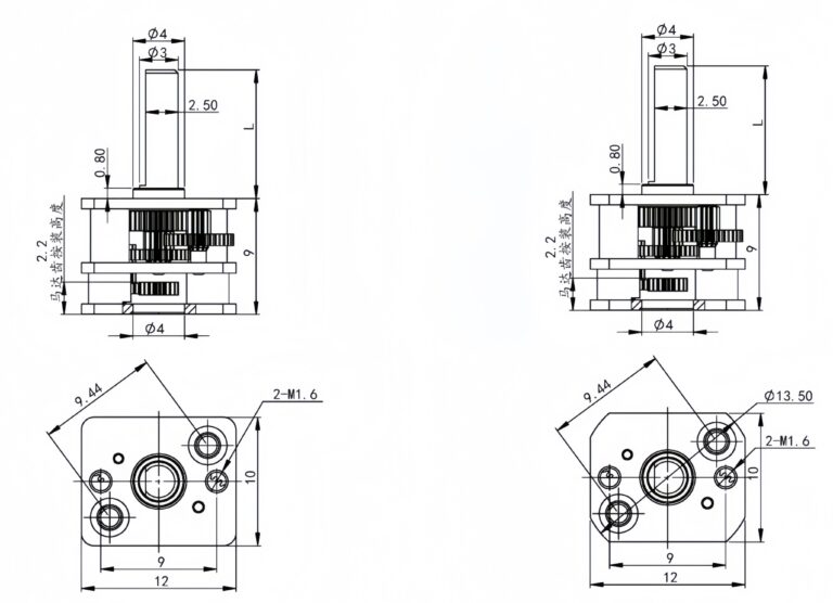
L9 supports compact builds; L12.5 supports deeper reductions and higher torque classes where stability margin is more critical.


Higher ratios are typically selected to increase torque margin while lowering output speed.

English

Japanese

Korean
Tell us about your project or application, and our team will get back to you with technical support, product recommendations, or a customized motor solution.