10mm Diameter Micro Brushled Coreless Motor With Planetary Gearbox And Encoder

This 10mm micro brushed coreless planetary gear motor with encoder is designed for 3–24V systems where you need low-speed control and feedback in a tight Φ10×L48 package, anchored by a 6V performance point.

Get a Quote
  • 10mm Diameter Micro Brushled Coreless Motor With Planetary Gearbox And Encoder Featured Image
Specs

Key Features

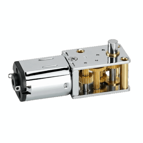
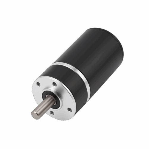
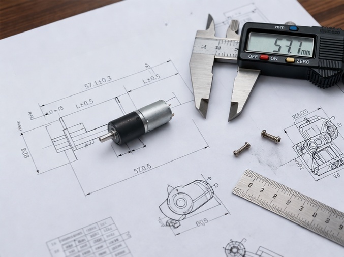
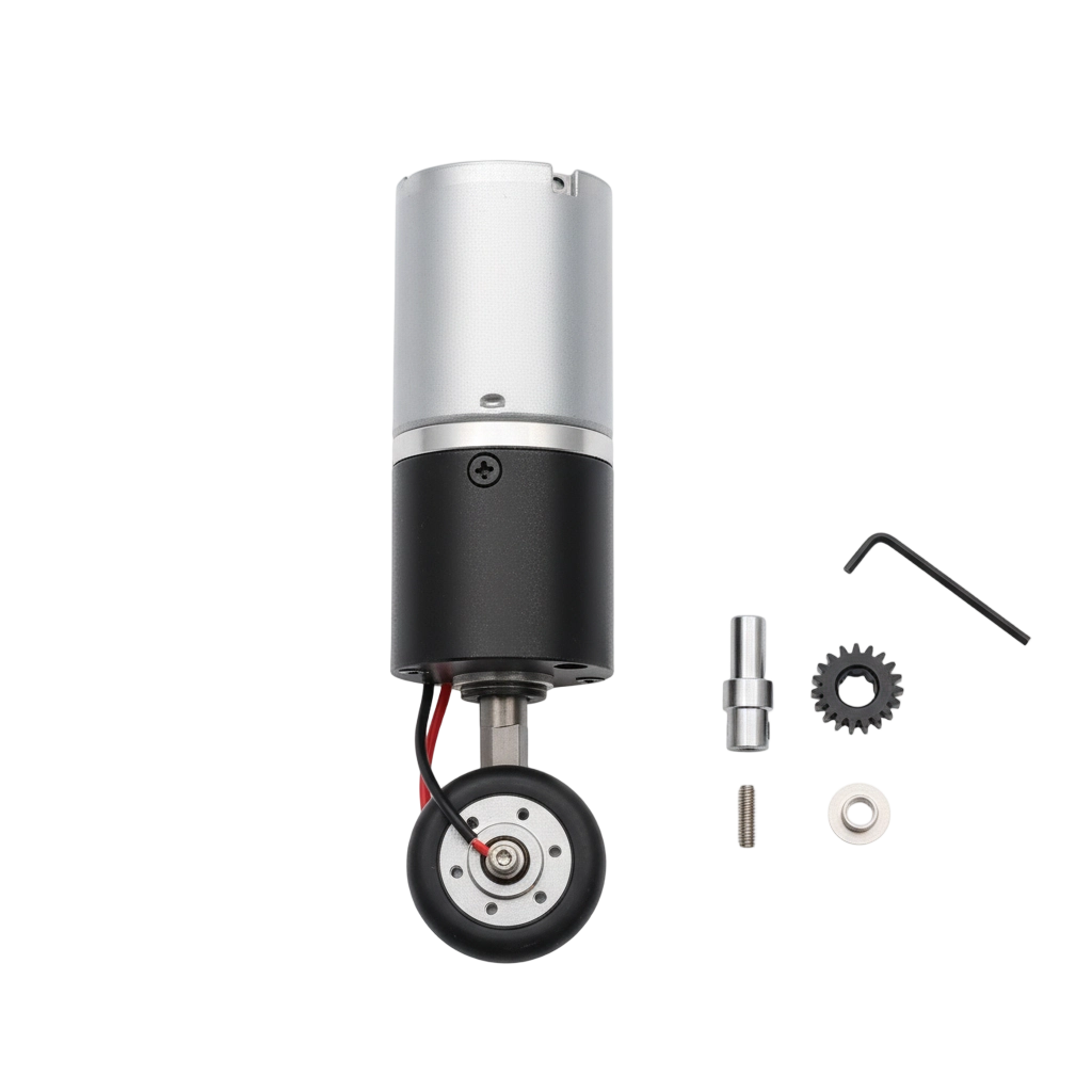
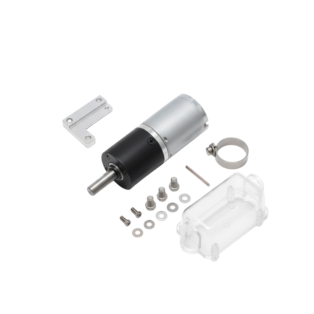
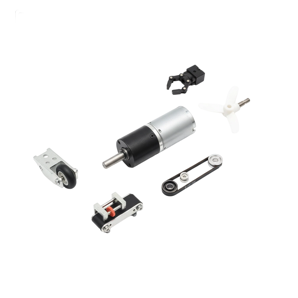
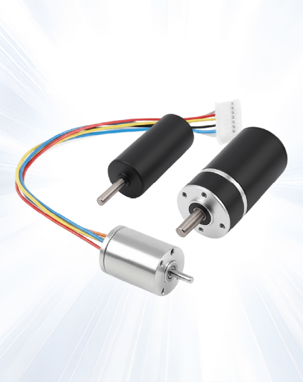
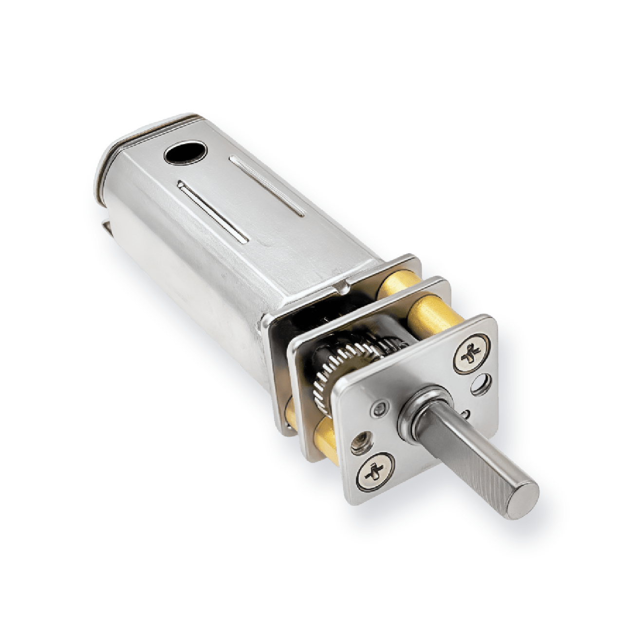
This model is a micro brushed coreless gear motor platform defined by its Φ10×L48 envelope, a low-speed rated operating point, and an integrated encoder interface that supports closed-loop motion in compact mechanisms.

  • 3V–24V applied range supports low-voltage battery and regulated DC architectures
  • 6V rated point provides a defined baseline for speed/current/torque planning in control loops
  • No-load speed is listed as 210 r/min ±12%, helping you set expected free-run speed before loading the mechanism
  • Rated speed is listed as 190 r/min ±12% with rated current 150 mA, supporting predictable driver sizing under working load
  • Stall torque is listed as 1500.0 g.cm with stall current 1.2 A, separating normal control current from fault or jam events
technical Specs

Motors Specifications

Motor Model Rated voltage No-load speed No-load current Rated speed Rated current Stall torque Stall current
VDC r/min mA r/min mA g.cm A
CLGM1023008 6V 210 ±12% 50 190 ±12% 150 1500 1.2

For additional customization or reference configurations, please feel free to contact us.

Why Choose us

SLW Motor Highlights

  • Low-Speed Control Baseline for Closed-Loop Systems

    The rated speed point at 190 r/min ±12% gives you a stable anchor for PID tuning and speed regulation when the mechanism runs under load.

  • Encoder-Ready Platform for Position and Speed Feedback

    The integrated encoder interface helps when your system must detect speed drift, count motion, or recover position after load changes.

  • Compact Φ10×L48 Envelope That Protects Mechanical Packaging

    This unit targets tight assemblies where motor diameter and total length constrain the design more than voltage range.

  • Stall Behavior Defines Protection and Jam Handling

    Stall torque and stall current create the boundary conditions for current limiting and fault recovery when the output is blocked or the mechanism jams.

Custom

Beyond the Standard: Performance Customized

  • 01
    Encoder Resolution and Signal Fit for Your Control Stack
    We confirm how you read feedback first (counting method and interface expectations), then align the encoder configuration so your controller can close the loop reliably.
  • 02
    Low-Speed Stability Under Load for Micro Mechanisms
    We map your required working speed to the rated-speed window and verify torque margin so the mechanism stays stable instead of hunting or stalling during load variation.
  • 03
    Stall-Event Containment at 1.2A
    We define your jam strategy first—current limit, timeout logic, and recovery behavior—because stall current is a step change from normal operating current.
  • 04
    Shaft and Output Engagement Planning in a Φ10 Form Factor
    We lock the usable shaft engagement and coupling method early to avoid slip or runout issues that become dominant at micro diameters.
  • 05
    Variant Strategy Across System Voltages (3–24V)
    If you build multiple SKUs, we keep the mechanical platform constant and only vary the electrical setup around your supply range while holding the 6V baseline as the reference point.
  • Encoder Resolution and Signal Fit for Your Control Stack
  • Low-Speed Stability Under Load for Micro Mechanisms
  • Stall-Event Containment at 1.2A
  • Shaft and Output Engagement Planning in a Φ10 Form Factor
  • Variant Strategy Across System Voltages (3–24V)

Custom Now

Related

Explore Our Motor

View All Products

FAQ

Frequently Asked Questions

If you share your available space and the driven load type, we can help narrow the most suitable configuration quickly.

How do I choose this model quickly for my mechanism?
Use the rated speed (190 r/min ±12%) as your target check first, then confirm stall current fits your driver protection and stall torque covers worst-case load.
Why do the speed values include ±12%?
The table defines an allowed tolerance window for speed so you can plan control margin and expected variation in real assemblies.
What does stall current change in my design?
It sets the peak-current boundary for wiring, driver current limit, and jam protection logic, which differs from normal operating current.
What should I share so you can shortlist suitability faster?
Share your target output speed, load torque estimate, duty cycle, available space, supply voltage, and whether you need speed-only or full position feedback.
Is it suitable for repeat production across variants?
Yes. You can standardize the Φ10×L48 platform and scale system variants mainly through voltage architecture and control settings.
Get Started

Accelerate Your Project with Precision Motors