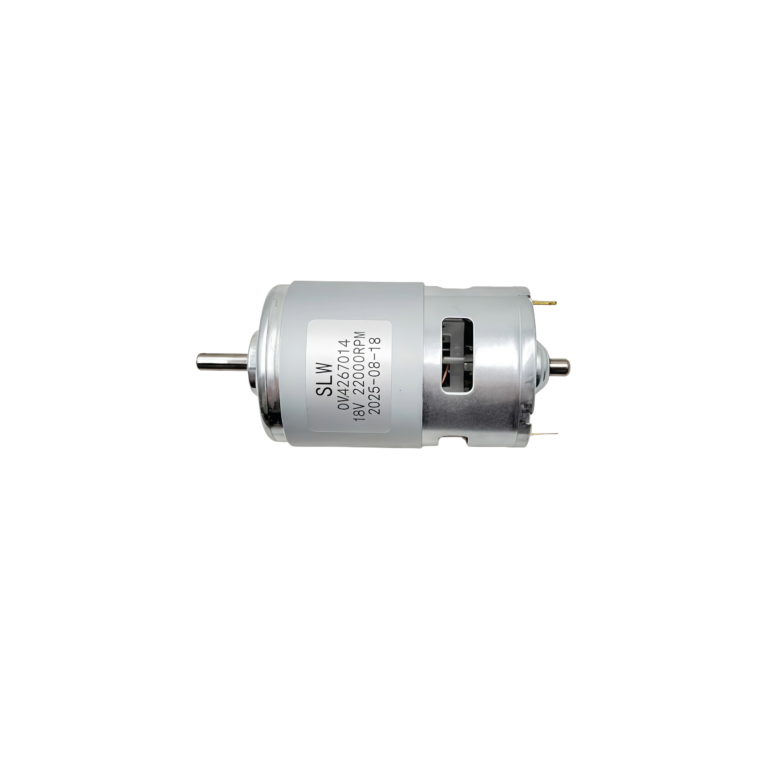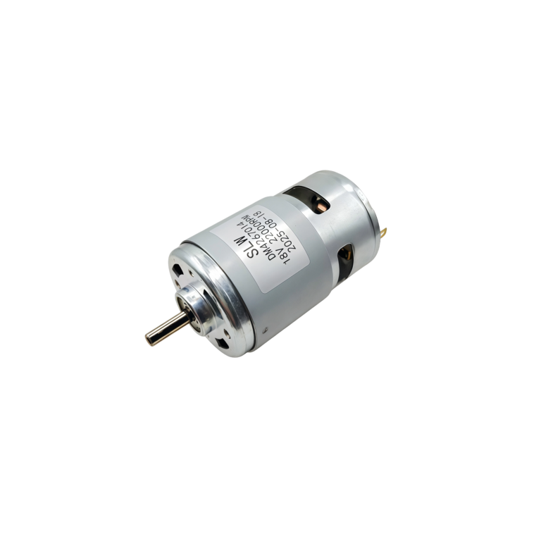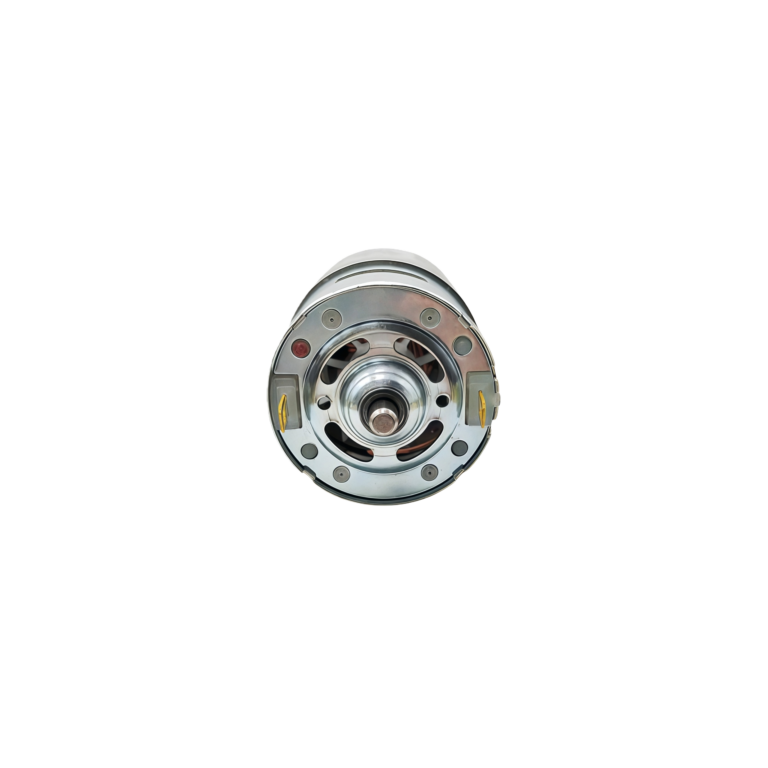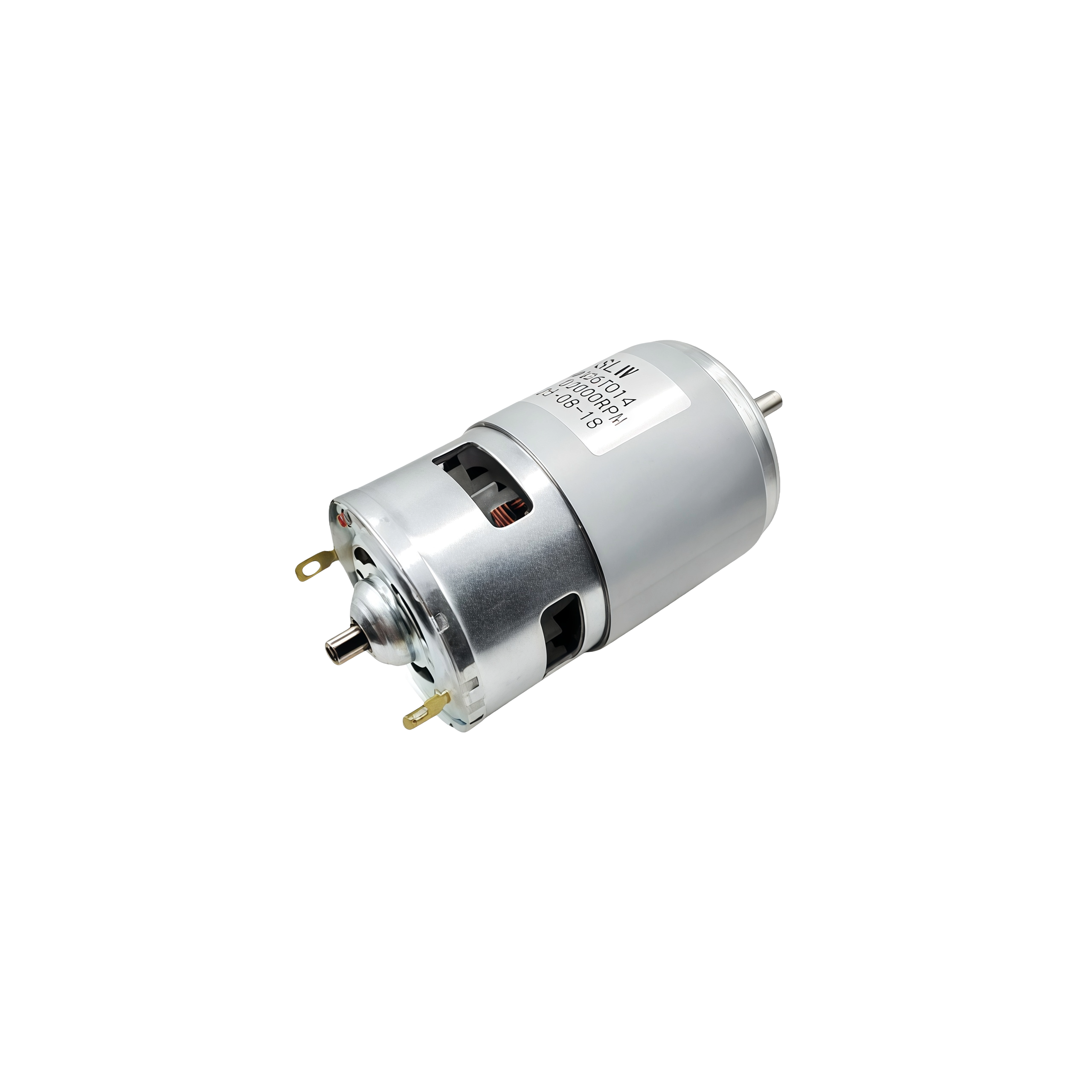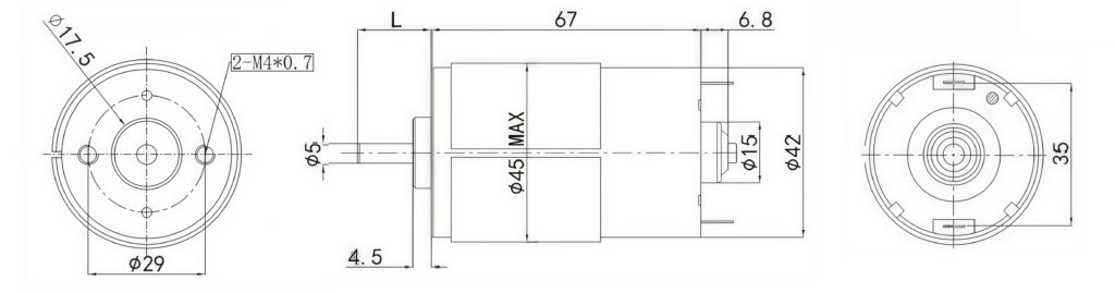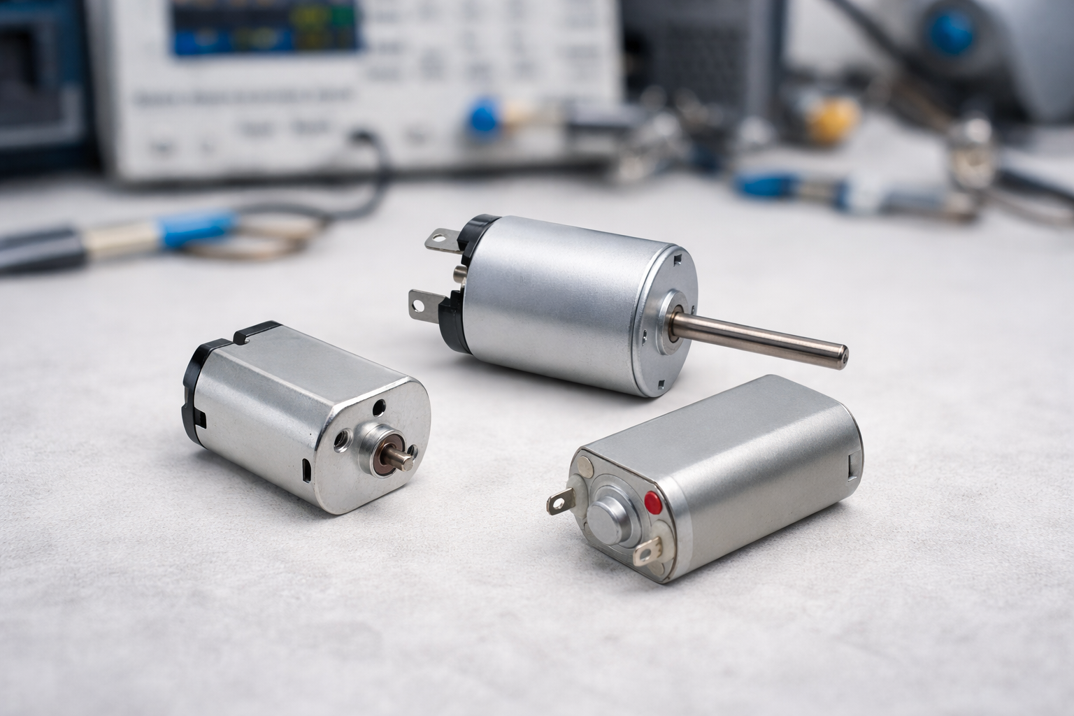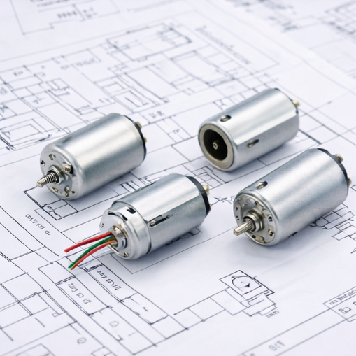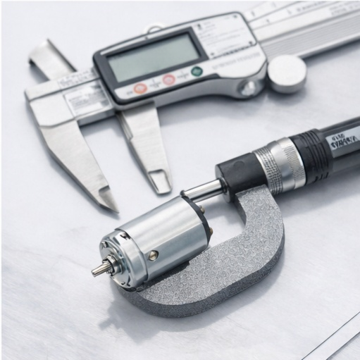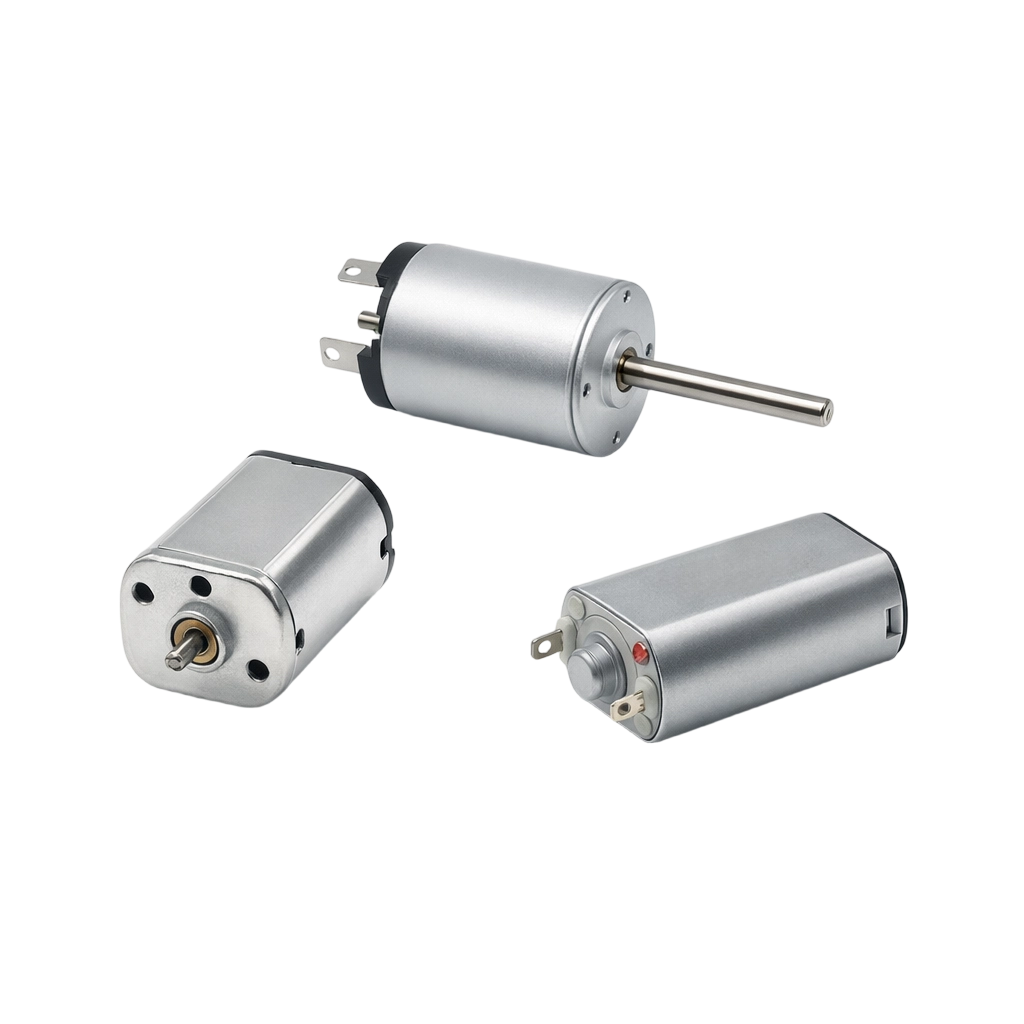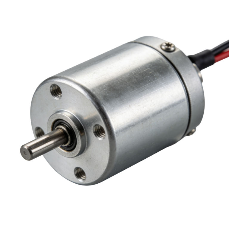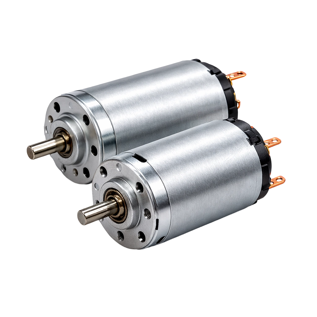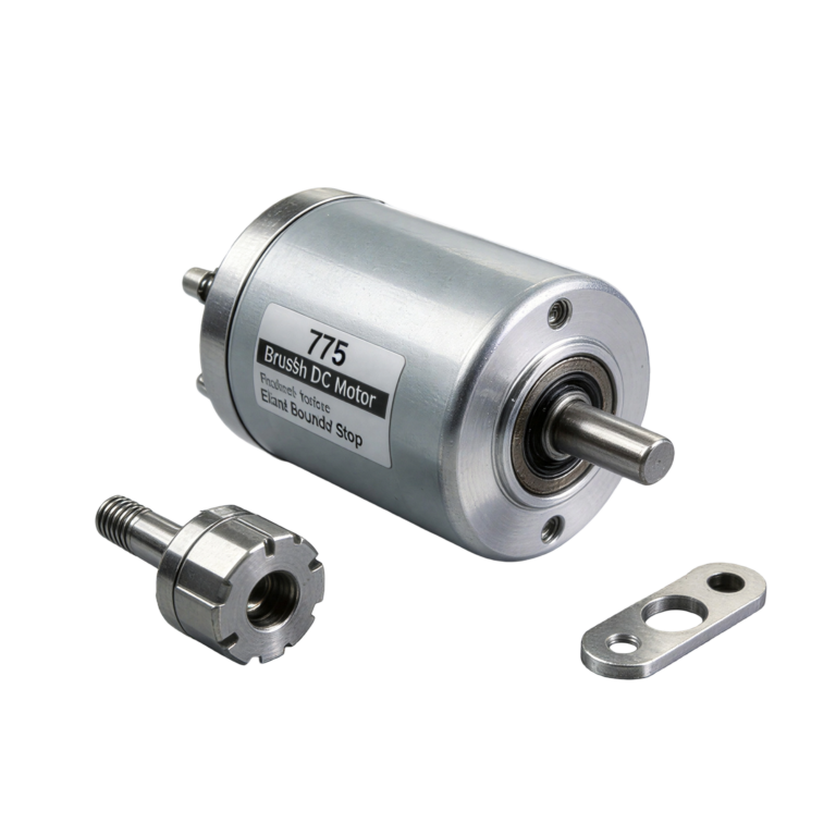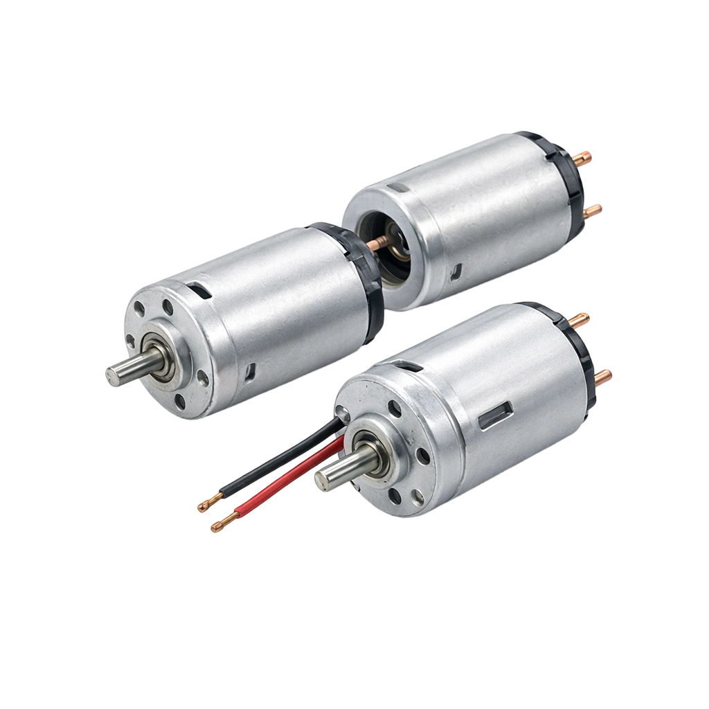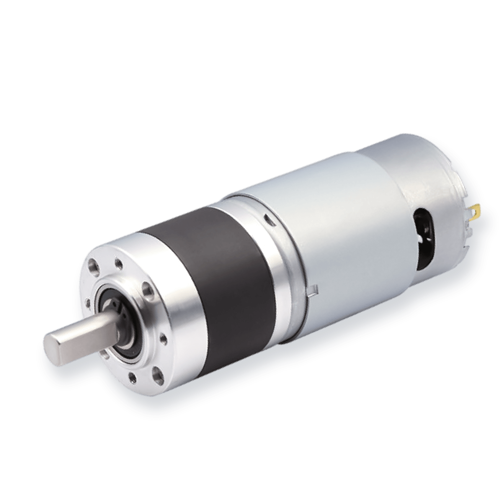
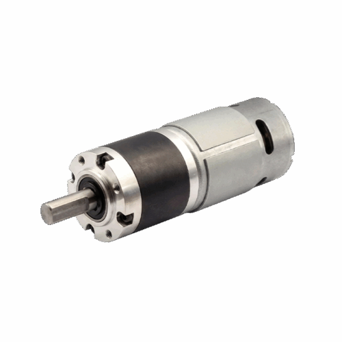
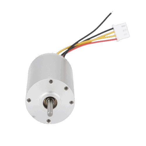
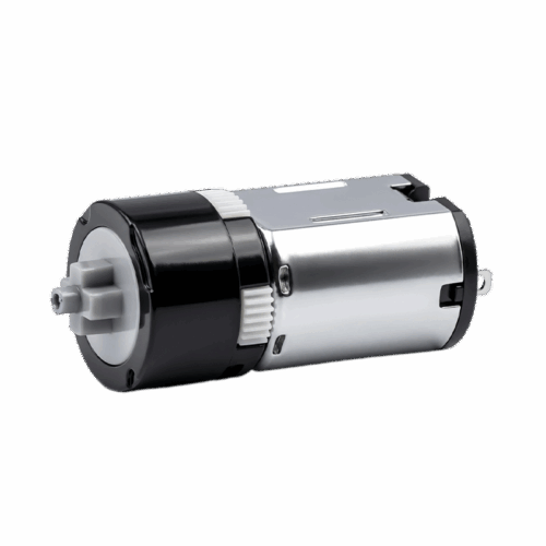


42mm Diameter 775 Brushed DC Motor
This 775 brushed DC motor is designed for 3–24V systems where you select between 18V and 24V windings, then size your driver and mechanics using a full curve table from no-load through max efficiency, max output, and stall.