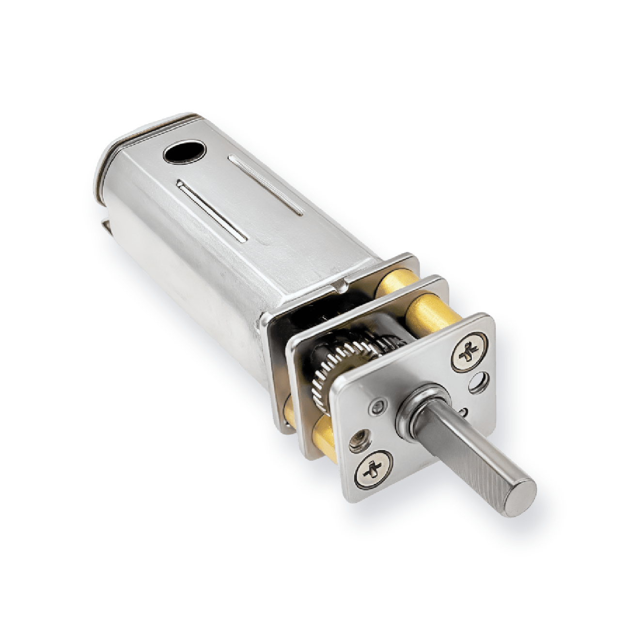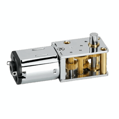
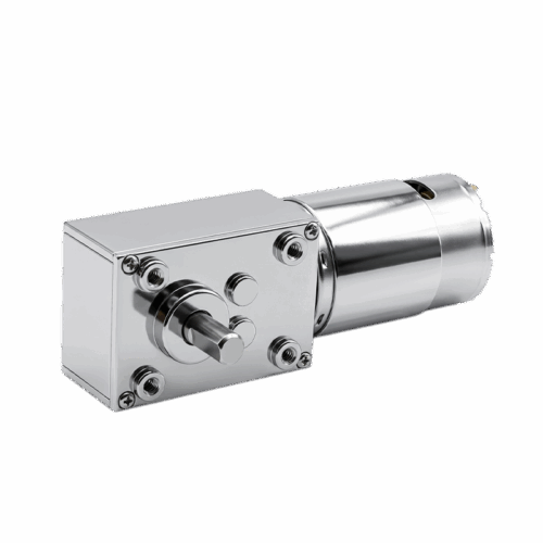
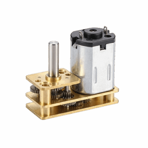
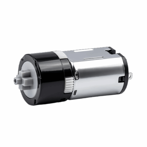


18mm Worm Gearbox & Reducer
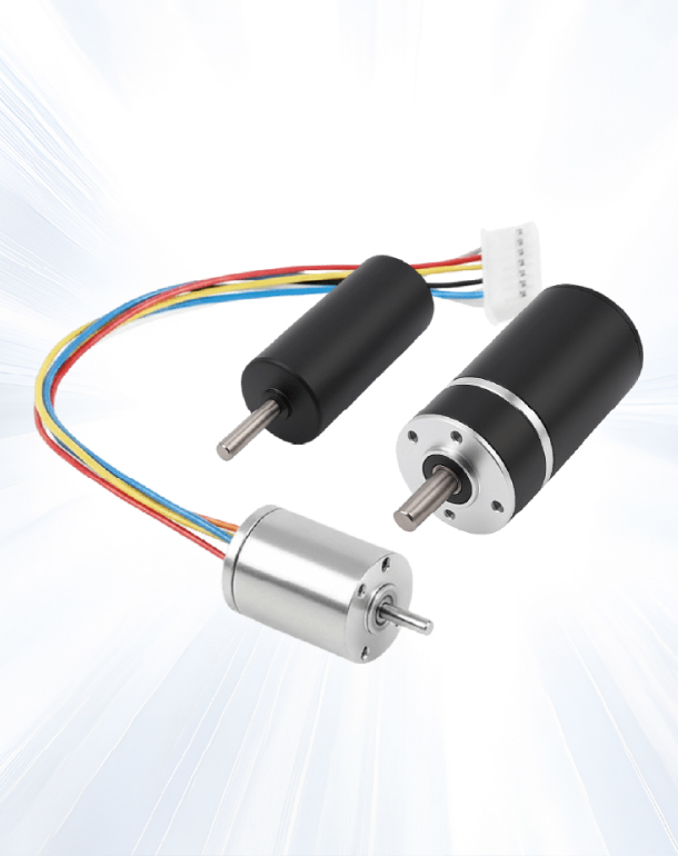
This 18mm worm gearbox is designed for compact drive systems that need high reduction ratios and stable low-speed output, with a customizable output shaft to support different coupling and mounting needs.


This 18mm worm gearbox is designed for compact drive systems that need high reduction ratios and stable low-speed output, with a customizable output shaft to support different coupling and mounting needs.


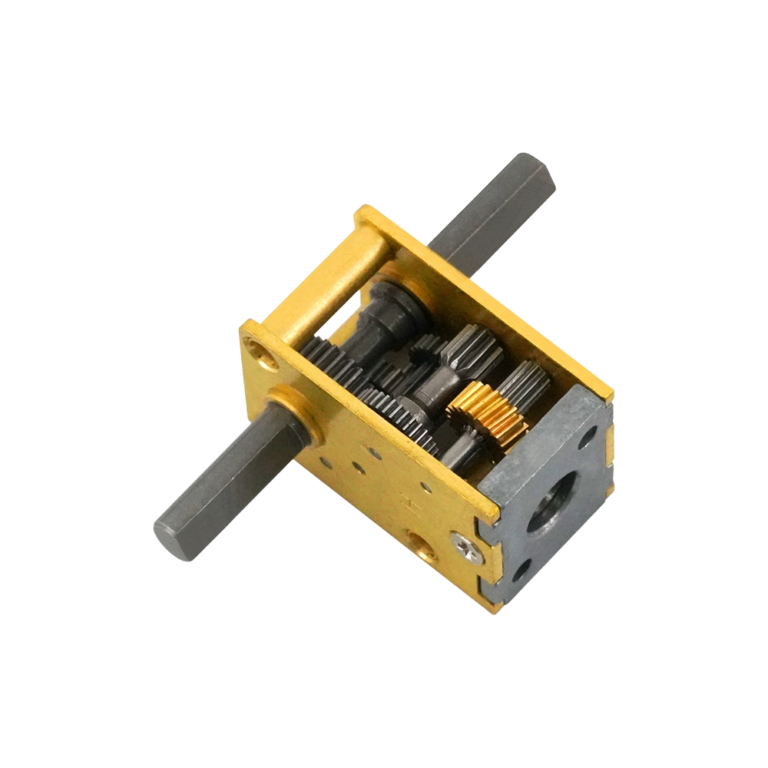
This worm gearbox uses a compact worm-drive structure to achieve higher reductions within a small package while keeping integration flexible.
| Index | Gear Ratio | Actual Ratio | Stages | Overall Size | Output Direction | Worm Starts | Worm ID (mm) | Single/Dual Output Shaft | Rated Torque (g·cm) | Allowable Peak Torque (g·cm) |
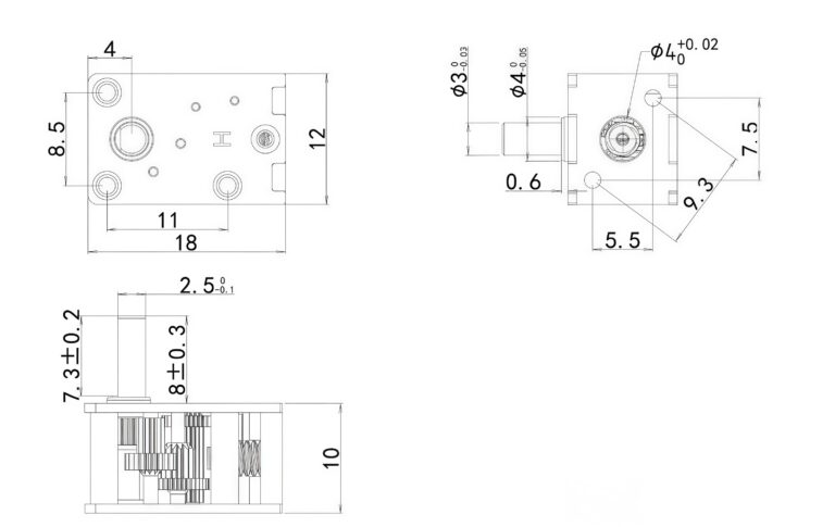
| 1 | 42 | 42.428 | 4 | 18*12*10 | Reverse | 3 | 1 | Single/Dual | 300 | 600 |
| 2 | 63 | 63.642 | 4 | 18*12*10 | Reverse | 2 | 1 | Single/Dual | 400 | 1200 |
| 3 | 80 | 80.808 | 4 | 18*12*10 | Reverse | 3 | 1 | Single | 400 | 1200 |
| 4 | 105 | 105.785 | 4 | 18*12*10 | Reverse | 3 | 1 | Single | 400 | 1200 |
| 5 | 118 | 117.483 | 4 | 18*12*10 | Reverse | 2 | 1 | Single/Dual | 400 | 1200 |
| 6 | 121 | 121.212 | 4 | 18*12*10 | Reverse | 2 | 1 | Single | 400 | 1200 |
| 7 | 127 | 127.285 | 4 | 18*12*10 | Reverse | 1 | 1 | Single/Dual | 400 | 1200 |
| 8 | 158 | 158.678 | 4 | 18*12*10 | Reverse | 2 | 1 | Single | 500 | 1500 |
| 9 | 200 | 201.399 | 5 | 18*12*10 | Same | 3 | 1 | Single/Dual | 600 | 1800 |
| 10 | 230 | 230.769 | 5 | 18*12*10 | Same | 3 | 1 | Single/Dual | 600 | 1800 |
| 11 | 235 | 234.956 | 4 | 18*12*10 | Reverse | 1 | 1 | Single/Dual | 600 | 1800 |
| 12 | 242 | 242.424 | 4 | 18*12*10 | Reverse | 1 | 1 | Single | 600 | 1800 |
| 13 | 302 | 302.098 | 5 | 18*12*10 | Same | 3/2 | 1 | Single/Dual | 800 | 2400 |
| 14 | 317 | 317.355 | 4 | 18*12*10 | Reverse | 1 | 1 | Single | 800 | 2400 |
| 15 | 343 | 343.802 | 5 | 18*12*10 | Same | 3 | 1 | Single | 800 | 2400 |
| 16 | 346 | 346.154 | 5 | 18*12*10 | Same | 2 | 1 | Single/Dual | 800 | 2400 |
| 17 | 453 | 453.147 | 5 | 18*12*10 | Same | 2 | 1 | Single/Dual | 800 | 2400 |
| 18 | 515 | 516.702 | 5 | 18*12*10 | Same | 2 | 1 | Single | 800 | 2400 |
| 19 | 584 | 584.222 | 5 | 18*12*10 | Same | 2 | 1 | Single | 800 | 2400 |
| 20 | 604 | 604.196 | 5 | 18*12*10 | Same | 1 | 1 | Single/Dual | 800 | 2400 |
| 21 | 692 | 692.308 | 5 | 18*12*10 | Same | 1 | 1 | Single/Dual | 800 | 2400 |
| 22 | 906 | 906.294 | 5 | 18*12*10 | Same | 1 | 1 | Single/Dual | 1000 | 3000 |
| 23 | 1031 | 1031.41 | 5 | 18*12*10 | Same | 1 | 1 | Single | 1000 | 3000 |
| 24 | 1047 | 1047.27 | 5 | 18*12*10 | Same | 1 | 1 | Single/Dual | 1000 | 3000 |
| 25 | 1350 | 1350.2 | 5 | 18*12*10 | Same | 1 | 1 | Single | 1000 | 3000 |
| 26 | 2025 | 2025.48 | 5 | 18*12*10 | Same | 1 | 1 | Single | 1000 | 3000 |
For additional customization or reference configurations, please feel free to contact us.


The 42–2025 ratio span supports slow-speed output targets without requiring a larger gearbox envelope.

Many ratio sets support single or dual output shafts, which helps when you need symmetric output or simplified linkage routing.

Different worm-start counts are used across the ratio set to balance reduction target and practical output characteristics within the same housing size.

Use rated torque for continuous sizing and treat allowable peak torque as a short-duration margin for start-up and brief load spikes.


Higher ratios are typically selected to increase torque margin while reducing output speed.

English

Japanese

Korean
Tell us about your project or application, and our team will get back to you with technical support, product recommendations, or a customized motor solution.