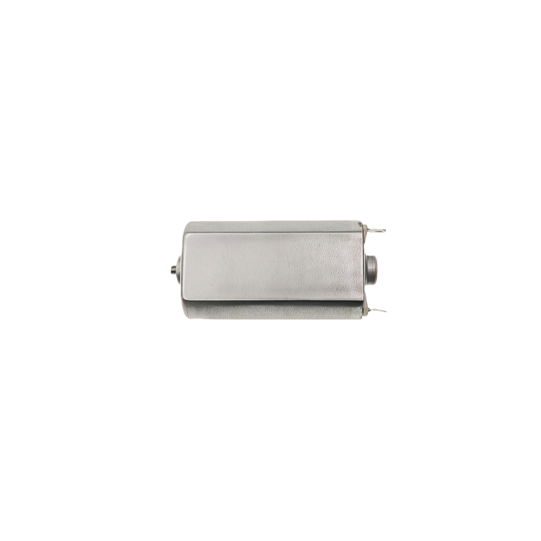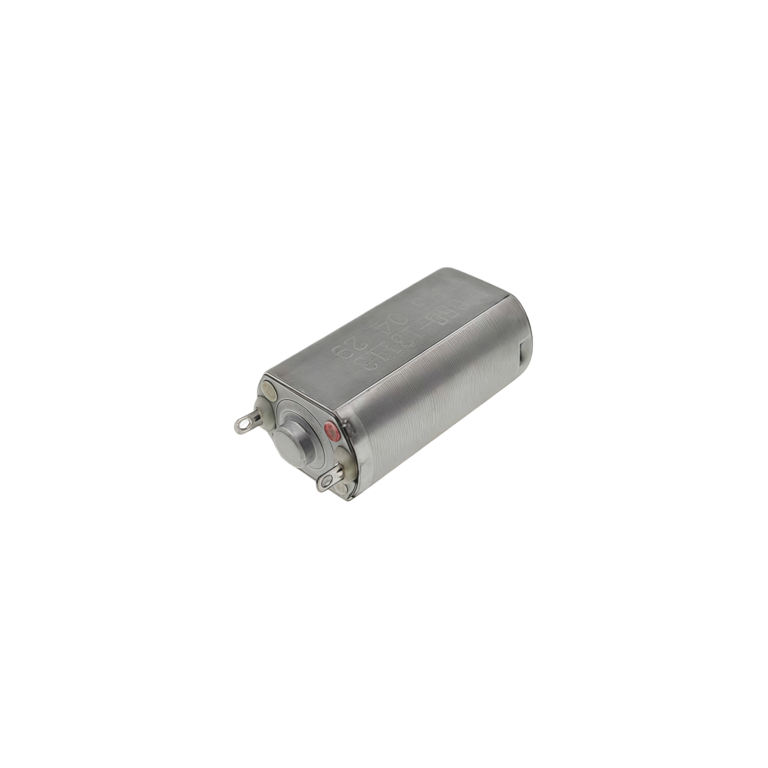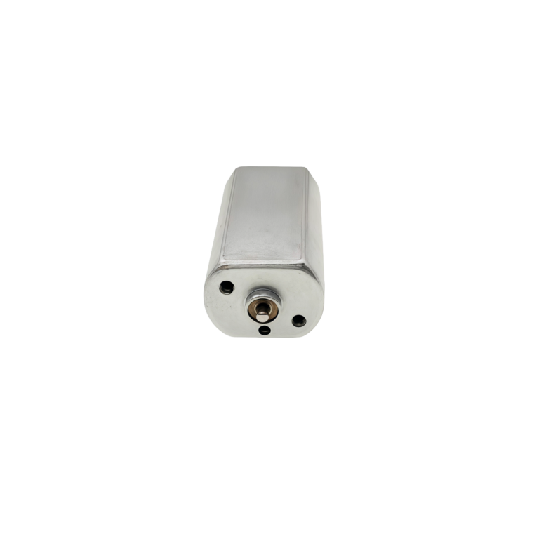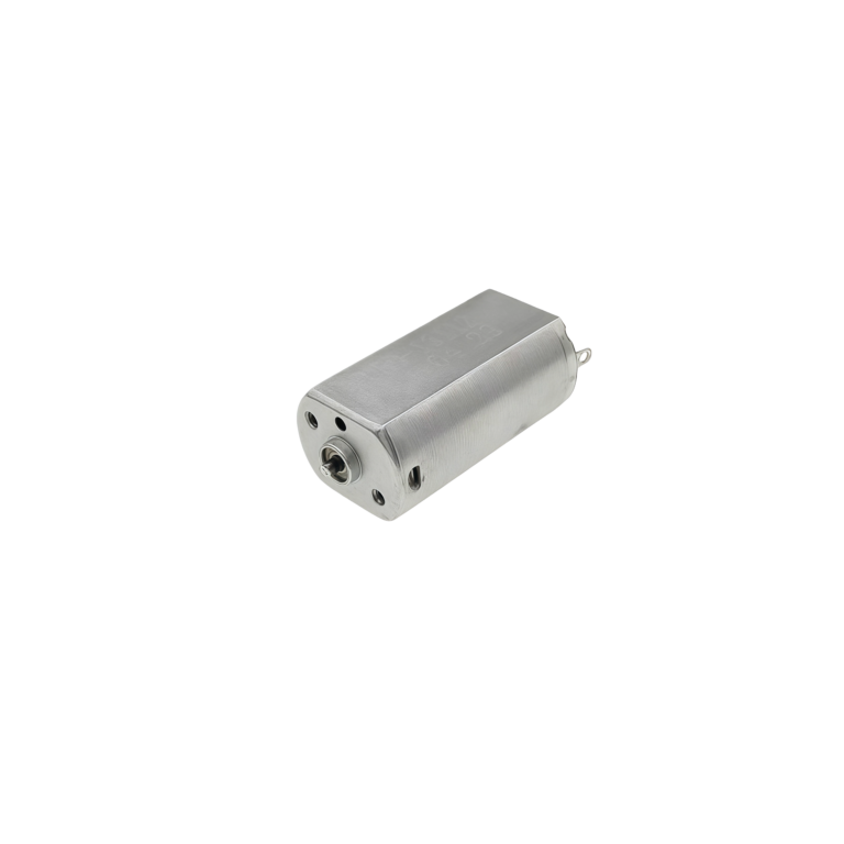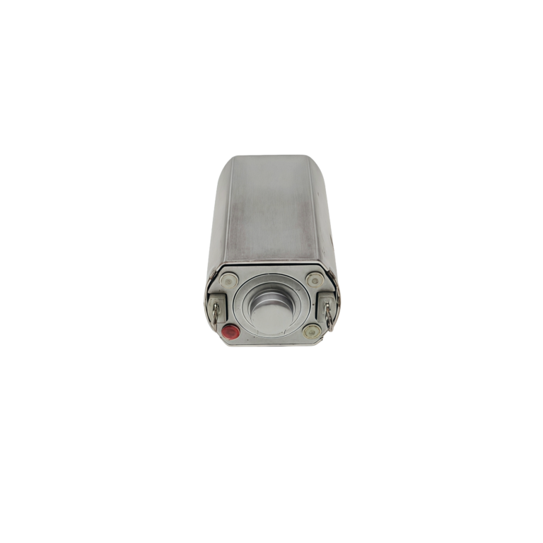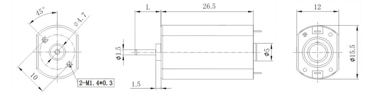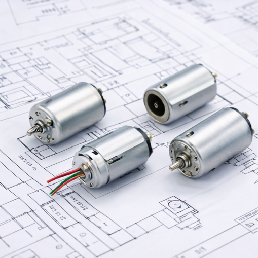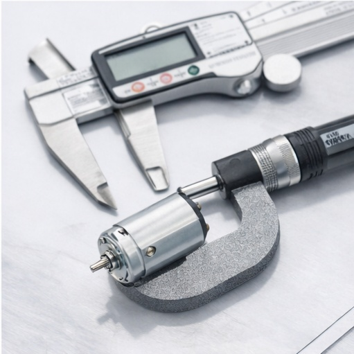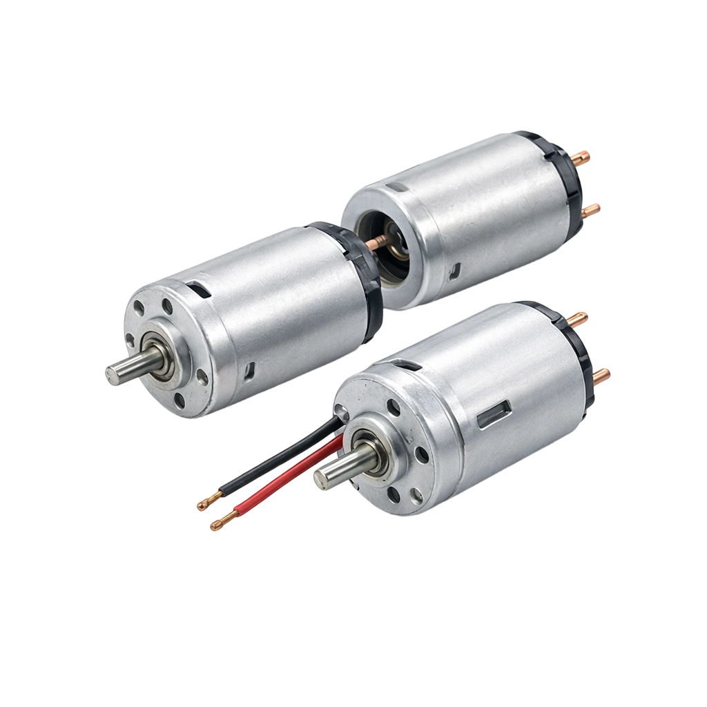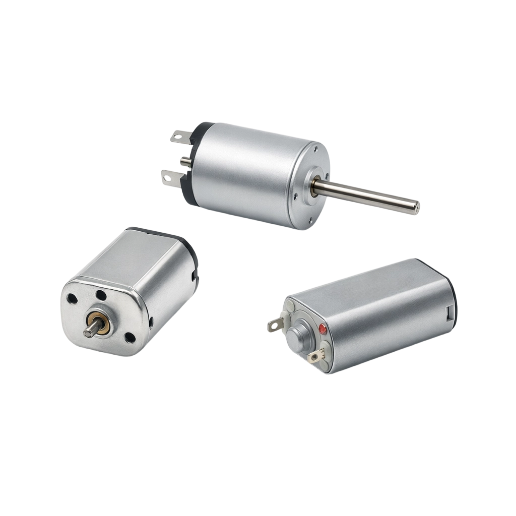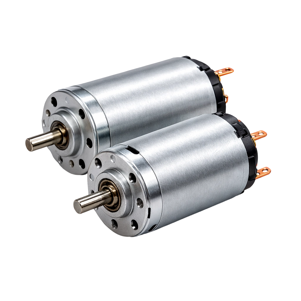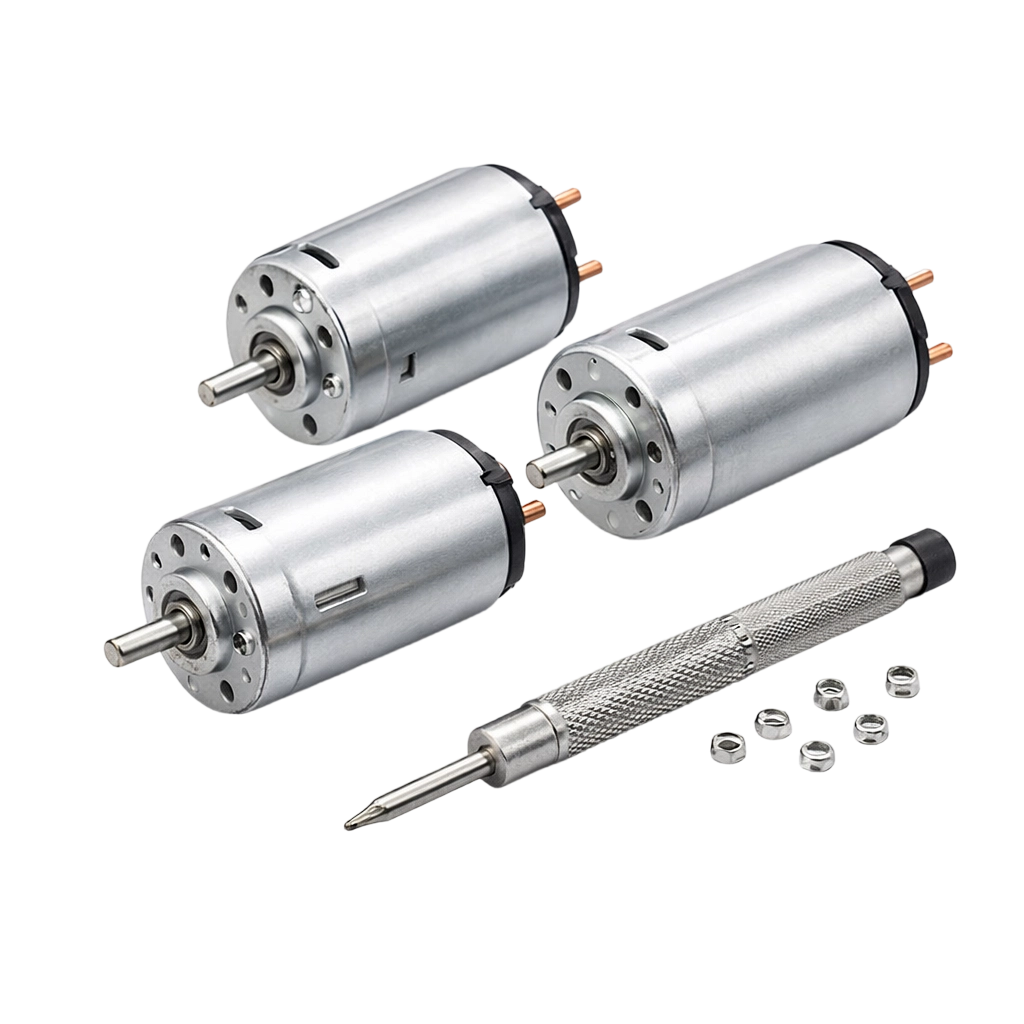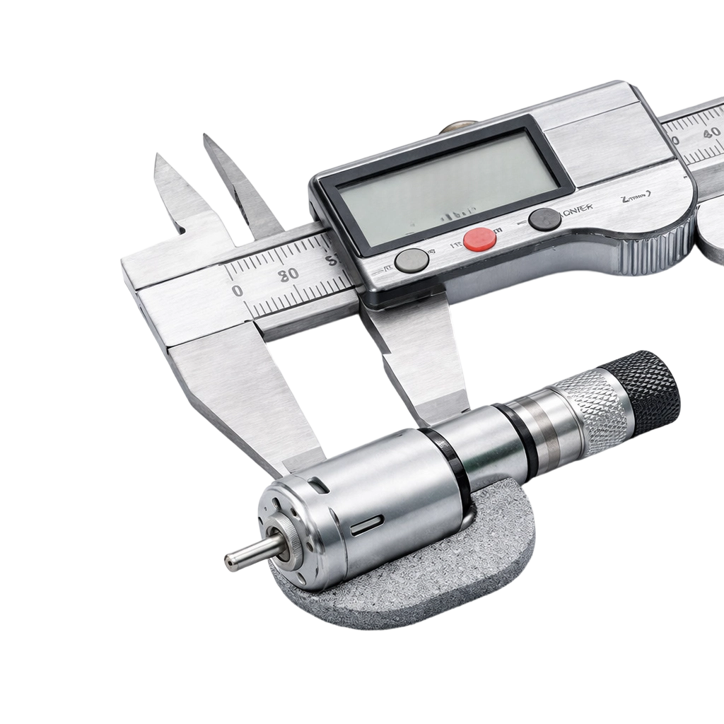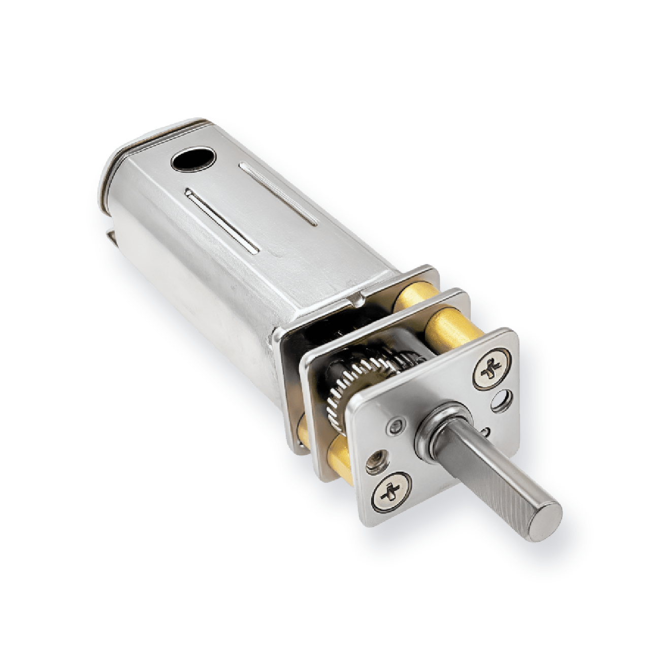
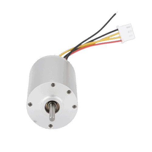
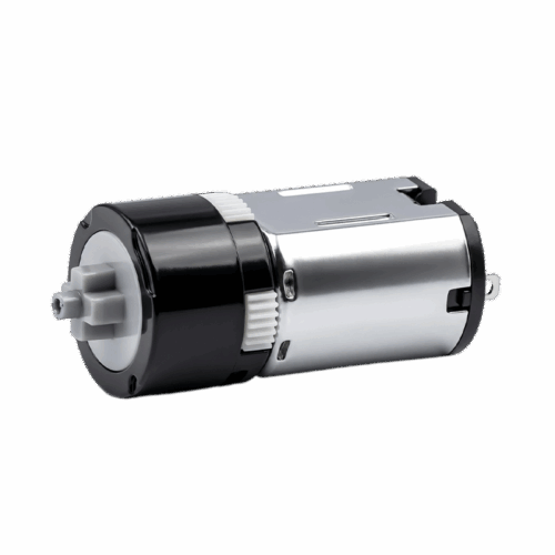


16mm Diameter 050 Micro Brushed DC Motor
This 050 brushed DC micro motor is designed for compact drives where you choose between two windings by voltage and speed class, then verify current draw and torque at no-load, max efficiency, max output, and stall points.