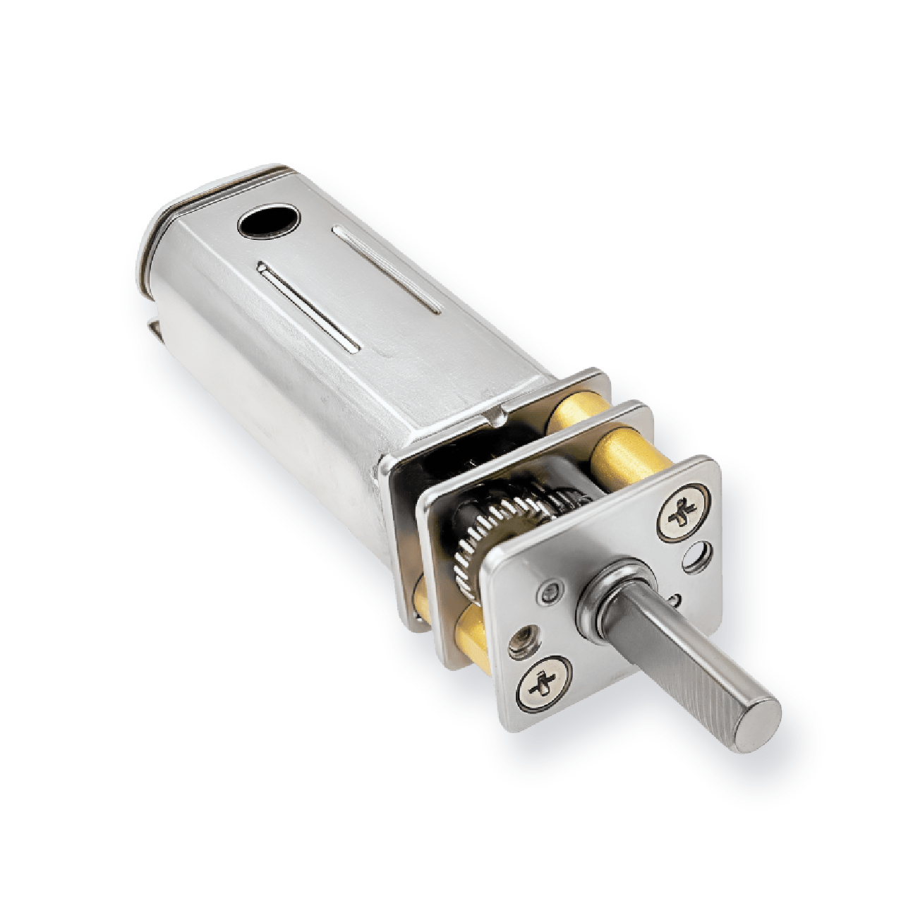
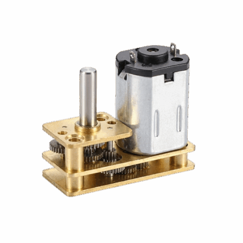
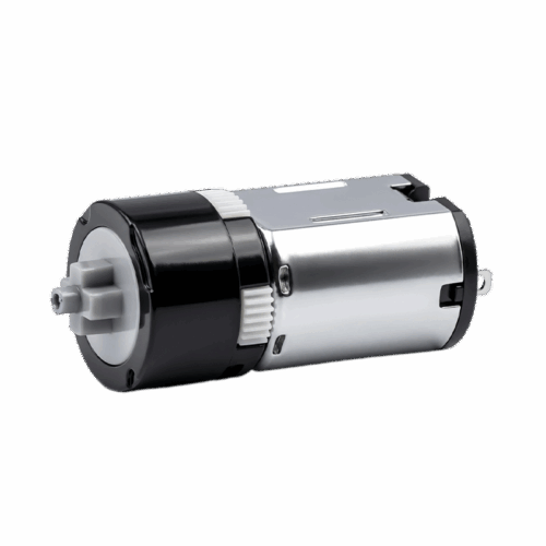


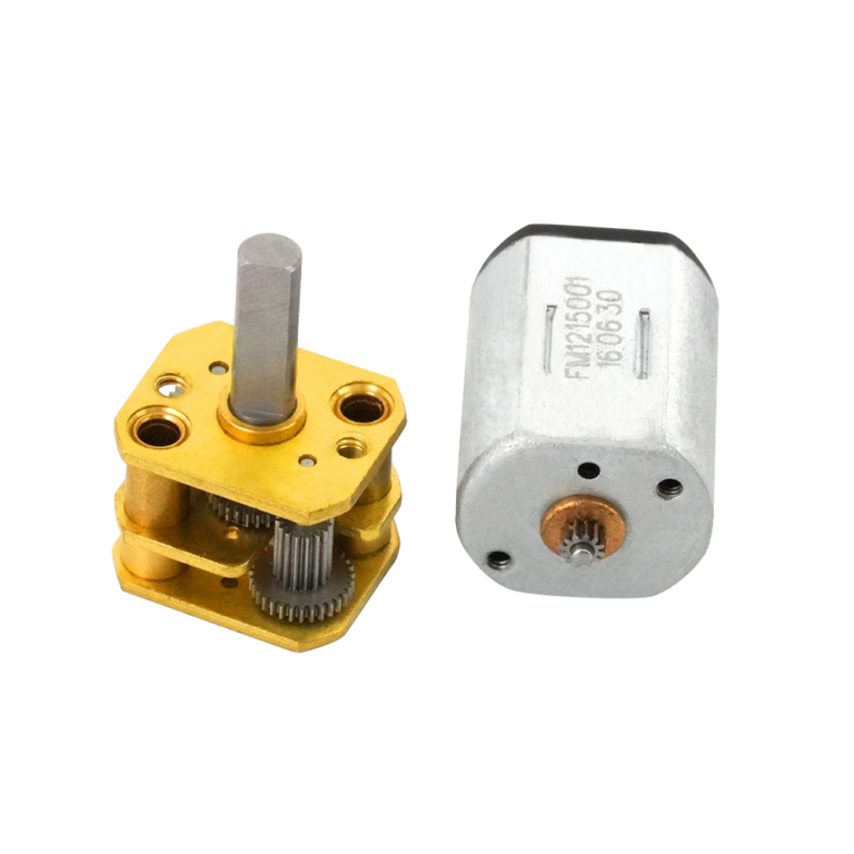
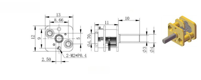
13mm Spur Gearbox & Reducer
This 13mm spur gearbox is designed for compact drive systems that require higher torque capacity and a broader mid-range ratio span, while keeping a stable mounting footprint and flexible output shaft integration.


This 13mm spur gearbox is designed for compact drive systems that require higher torque capacity and a broader mid-range ratio span, while keeping a stable mounting footprint and flexible output shaft integration.


This spur gearbox adopts a gear-hobbing structure to balance torque capacity and layout stability in compact transmission systems.
| Index | Gear Ratio | Actual Ratio | Stages | Overall Size | Output Direction | Motor Gear Teeth | Motor Gear ID (mm) | Rated Torque (g·cm) | Allowable Peak Torque (g·cm) |
| 1 | 6 | 5.579 | 2 | 13*12*11 | Same | 15 | 1.5 | 200 | 600 |
| 2 | 9 | 9.007 | 2 | 13*12*11 | Same | 15 | 1.5 | 200 | 600 |
| 3 | 16 | 16.111 | 3 | 13*12*11 | Reverse | 15 | 1.5 | 300 | 900 |
| 4 | 20 | 20.092 | 3 | 13*12*11 | Reverse | 15 | 1.5 | 300 | 900 |
| 5 | 26 | 26.092 | 3 | 13*12*11 | Reverse | 15 | 1.5 | 300 | 900 |
| 6 | 30 | 29.774 | 3 | 13*12*11 | Reverse | 15 | 1.5 | 300 | 900 |
| 7 | 35 | 35.61 | 4 | 13*12*11 | Same | 15 | 1.5 | 300 | 900 |
| 8 | 52 | 52.576 | 4 | 13*12*11 | Same | 15 | 1.5 | 400 | 1200 |
| 9 | 67 | 67.093 | 4 | 13*12*11 | Same | 15 | 1.5 | 400 | 1200 |
| 10 | 85 | 84.877 | 4 | 13*12*11 | Same | 15 | 1.5 | 500 | 1500 |
| 11 | 100 | 99.982 | 4 | 13*12*11 | Same | 15 | 1.5 | 600 | 1800 |
| 12 | 118 | 117.712 | 5 | 13*12*11 | Reverse | 15 | 1.5 | 600 | 1800 |
| 13 | 150 | 151.813 | 5 | 13*12*11 | Reverse | 15 | 1.5 | 600 | 1800 |
| 14 | 170 | 173.793 | 5 | 13*12*11 | Reverse | 15 | 1.5 | 600 | 1800 |
| 15 | 215 | 214.771 | 5 | 13*12*11 | Reverse | 15 | 1.5 | 700 | 2100 |
| 16 | 250 | 253.097 | 5 | 13*12*11 | Reverse | 15 | 1.5 | 700 | 2100 |
| 17 | 297 | 297.071 | 5 | 13*12*11 | Reverse | 15 | 1.5 | 700 | 2100 |
| 18 | 330 | 330.767 | 5 | 13*12*11 | Reverse | 15 | 1.5 | 800 | 2400 |
| 19 | 360 | 359.118 | 5 | 13*12*11 | Reverse | 15 | 1.5 | 800 | 2400 |
For additional customization or reference configurations, please feel free to contact us.


The 13mm form factor increases torque capacity compared with smaller gearboxes, making it suitable for more demanding compact mechanisms.

Lower ratios support faster output motion, while higher ratios focus on torque margin and smoother low-speed behavior.

As ratios increase, additional stages help maintain transmission stability without changing the external footprint.

Custom shaft interfaces help control slip and alignment when transmitting higher torque levels in small assemblies.


Higher ratios are typically selected to increase torque capacity while reducing output speed.

English

Japanese

Korean
Tell us about your project or application, and our team will get back to you with technical support, product recommendations, or a customized motor solution.