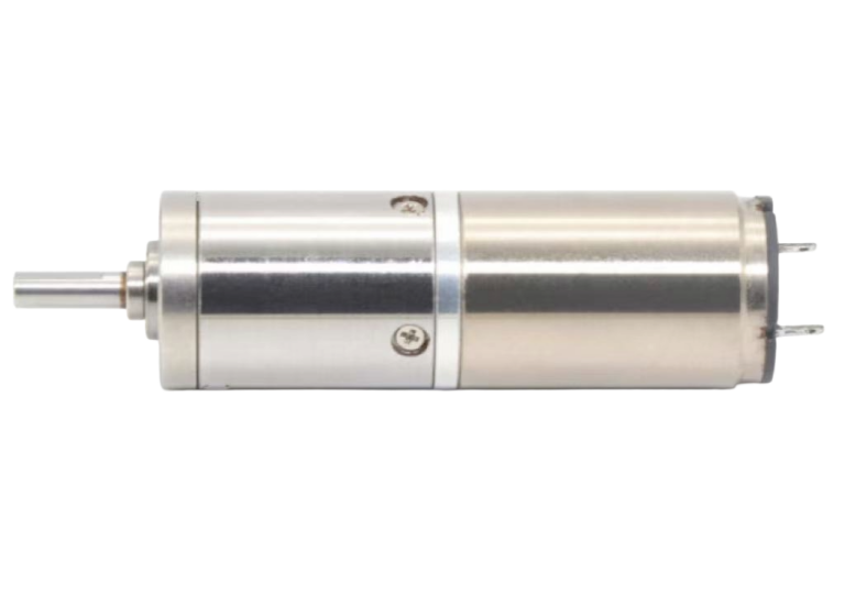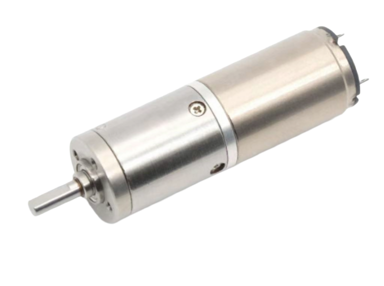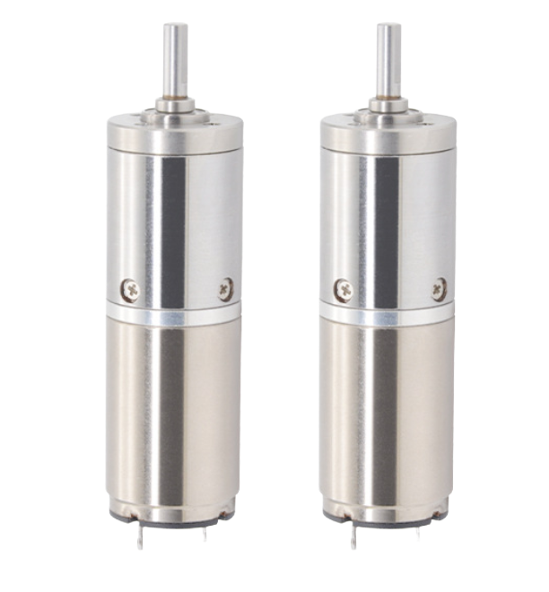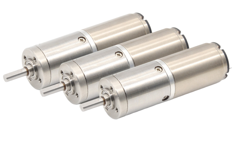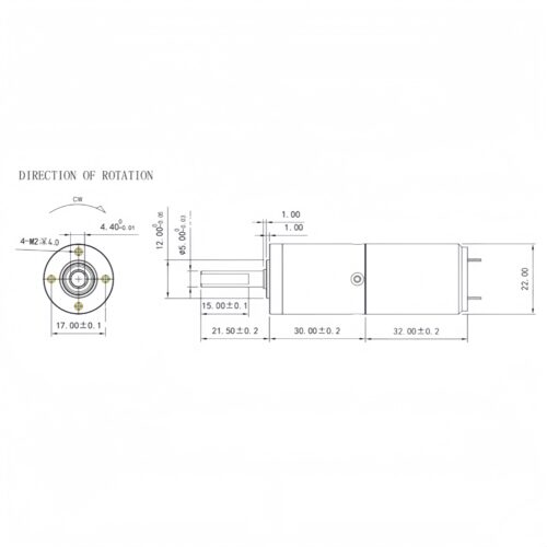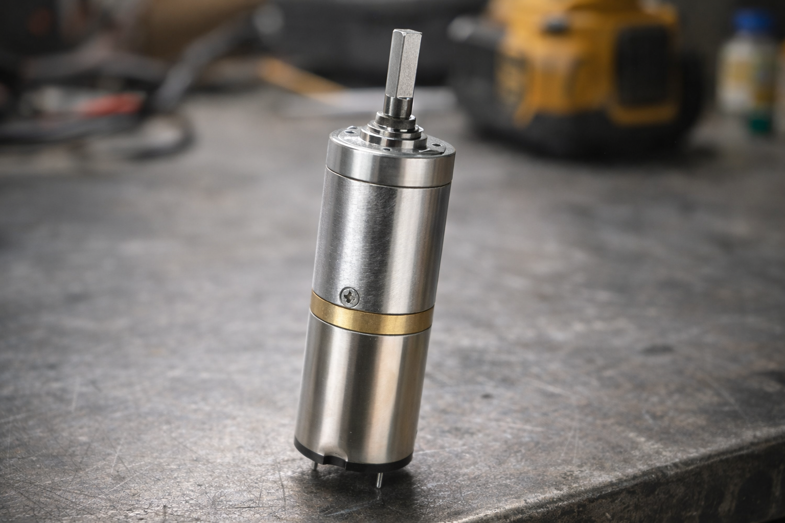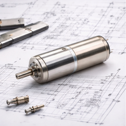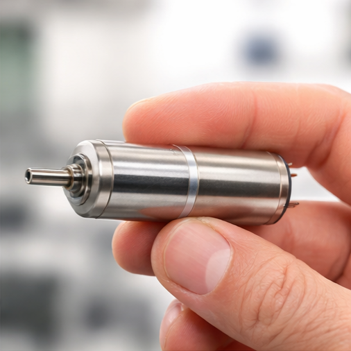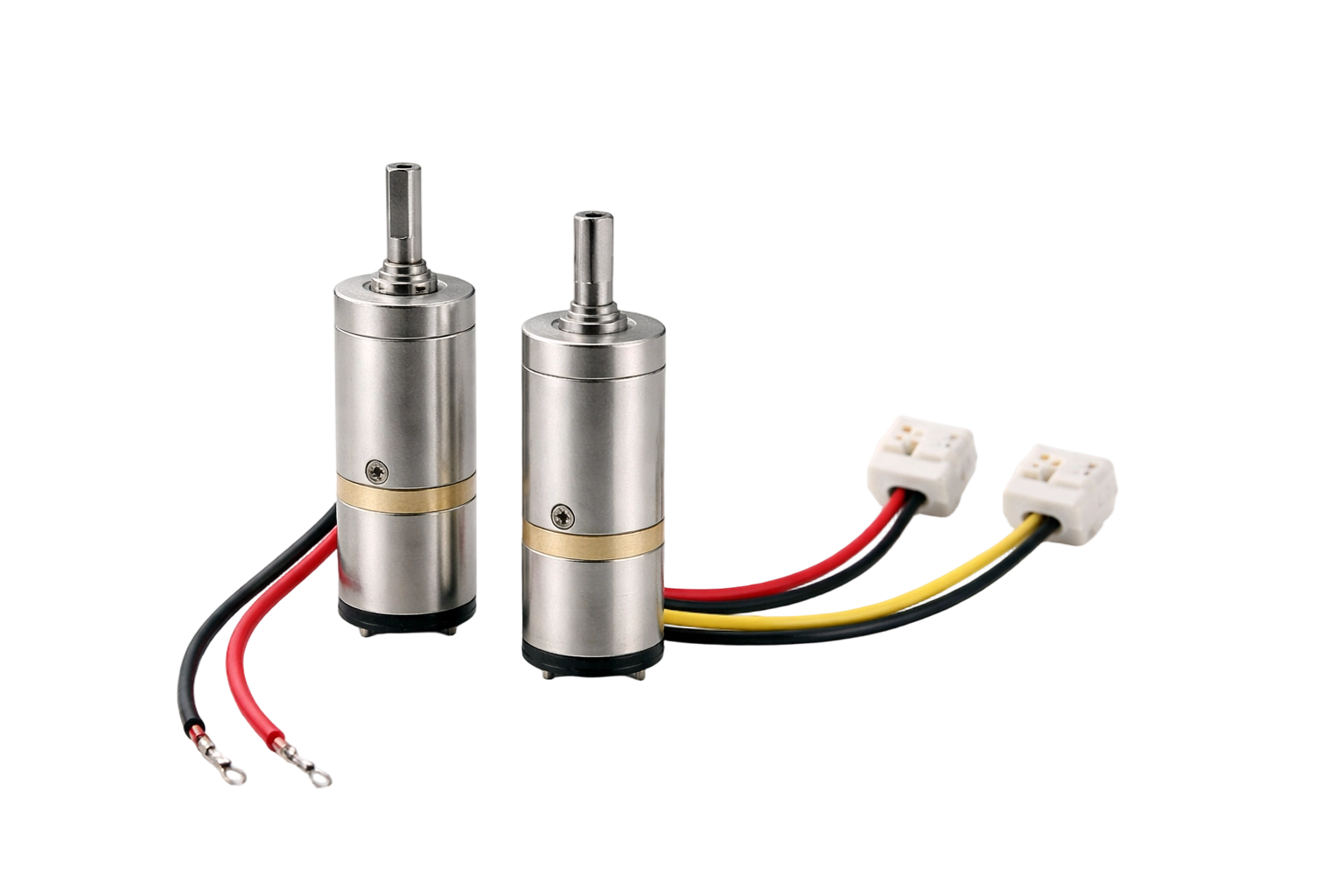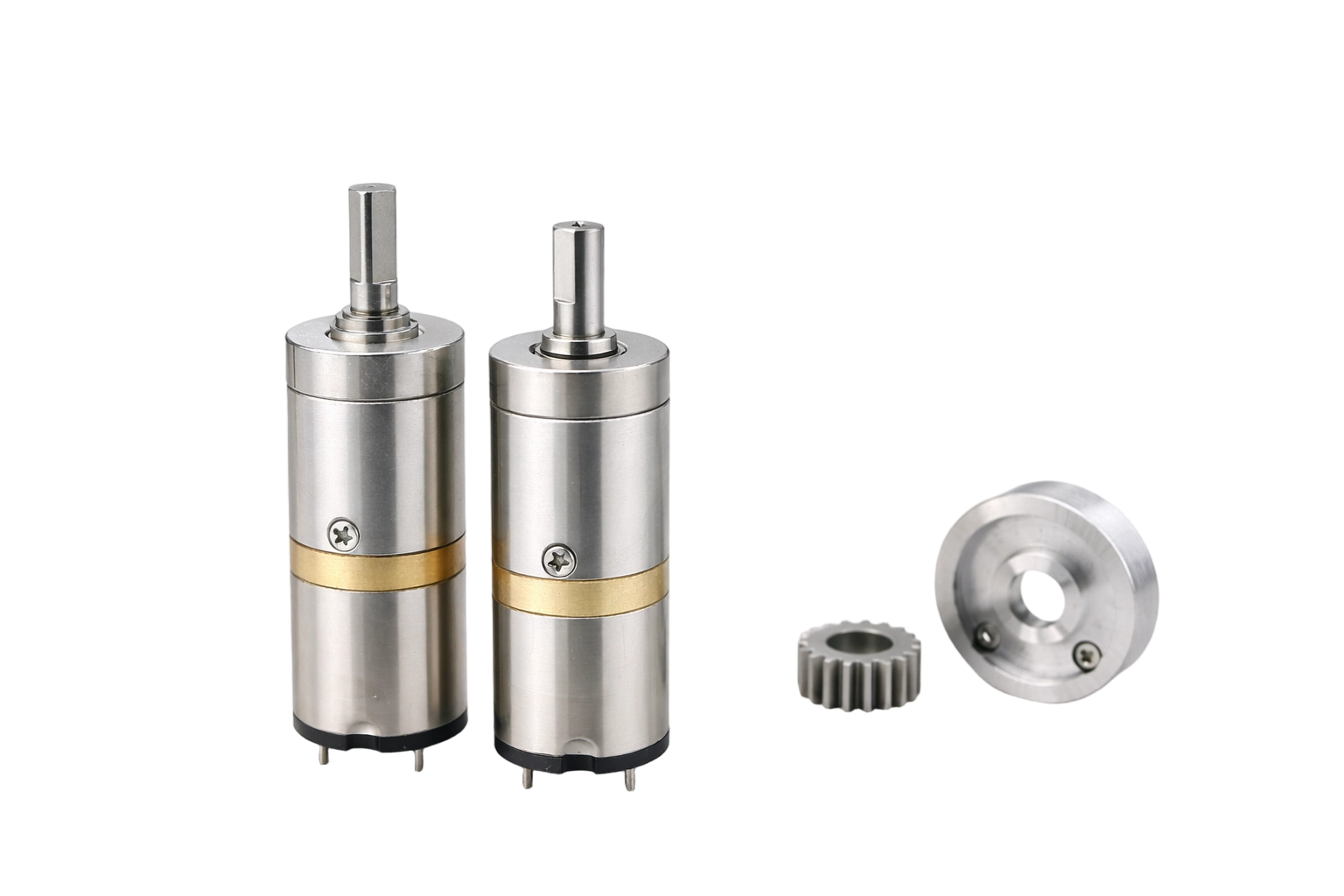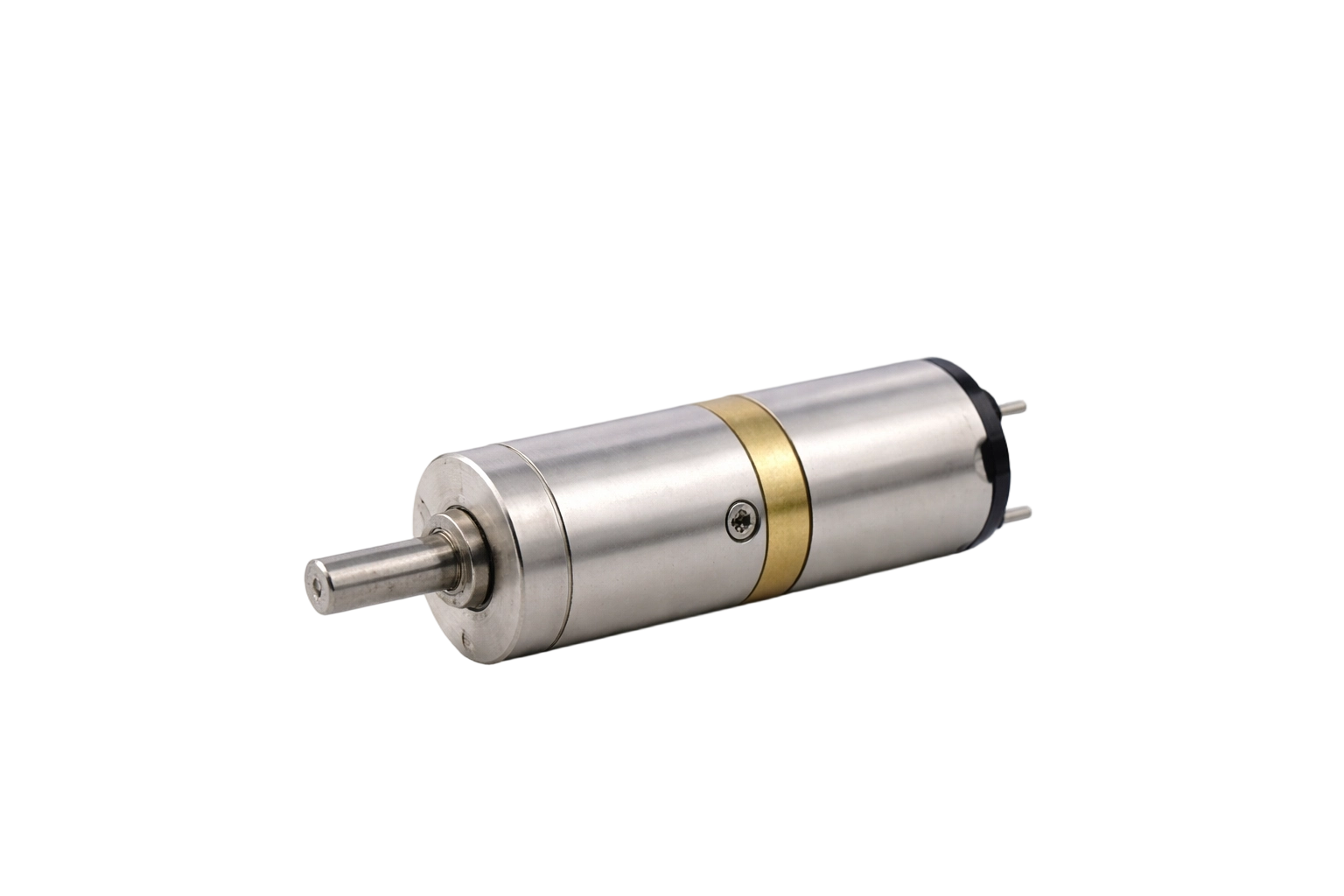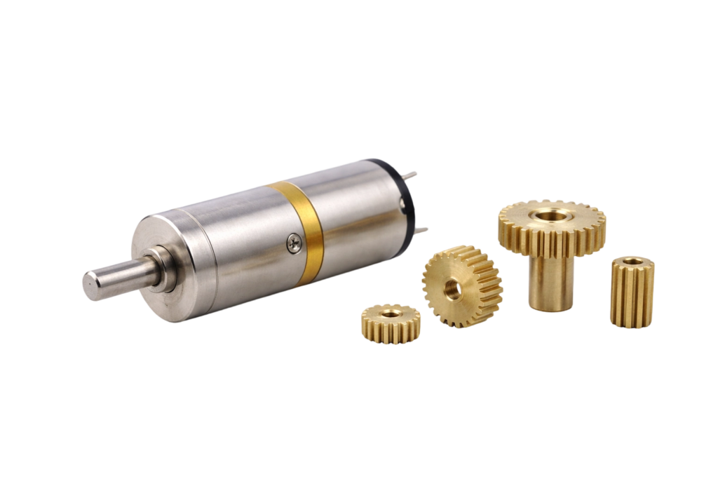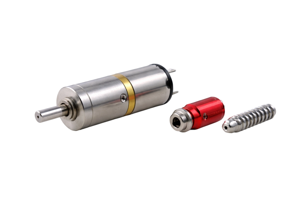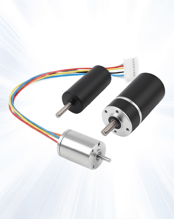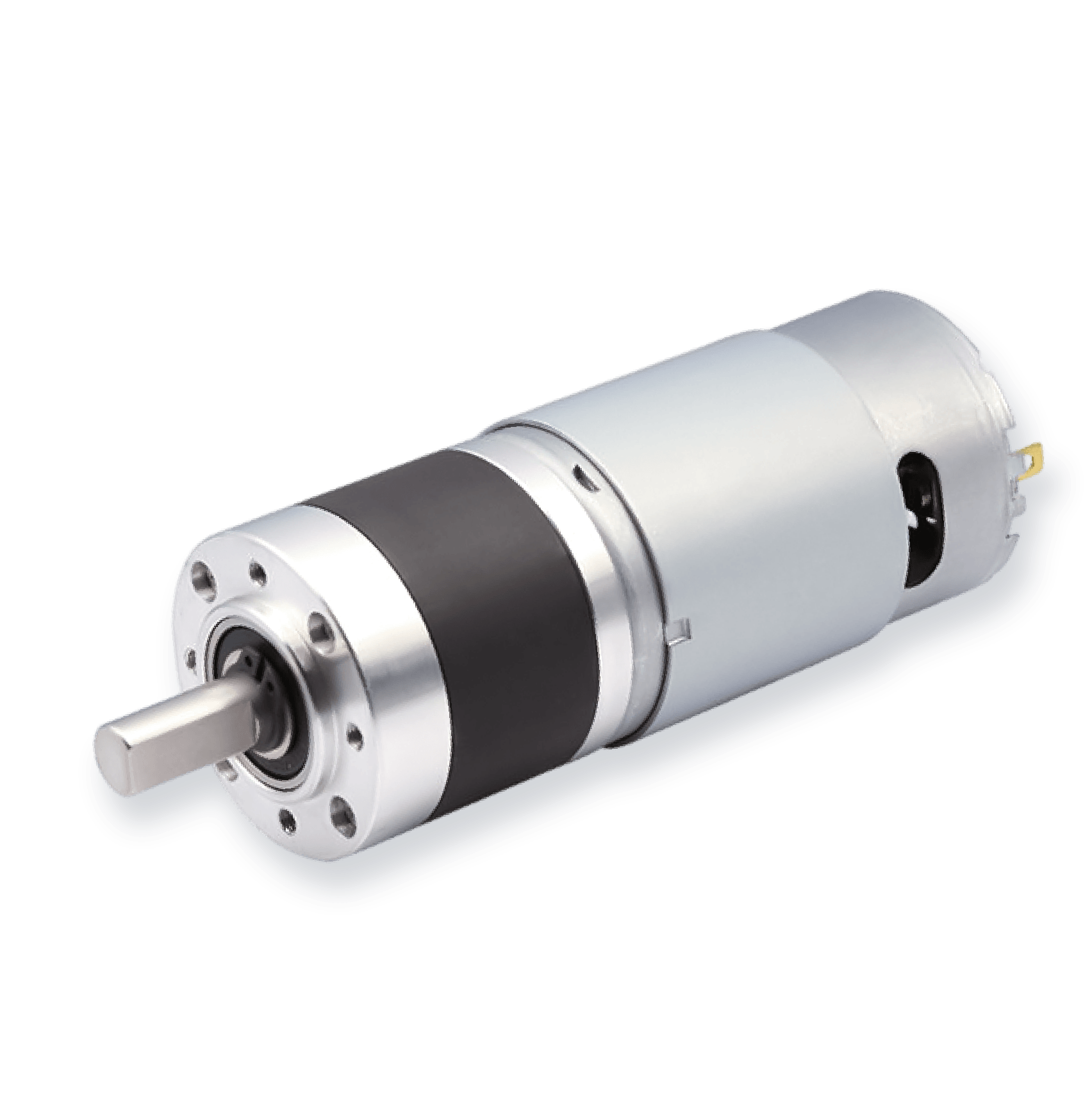
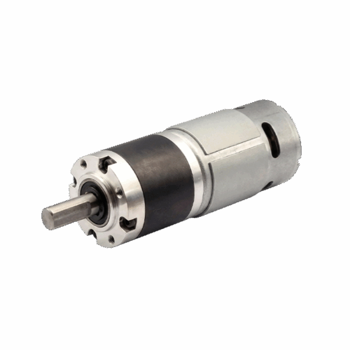
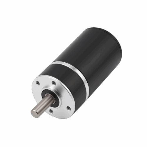
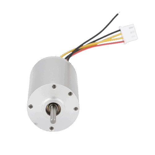
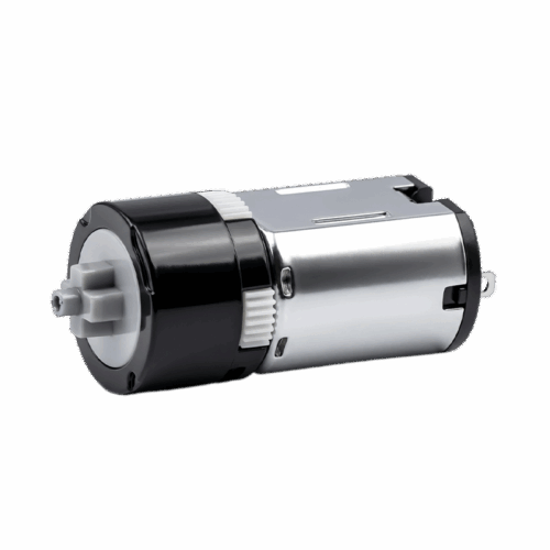


22mm Diameter DC Brushed Coreless Motor With Planetary Gearbox
This 22mm brushed coreless planetary gear motor is designed for 6–24V systems where you need an ultra-low-speed output around 9–10 rpm in a Φ22 gearbox envelope, with current capped by “MAX” limits.