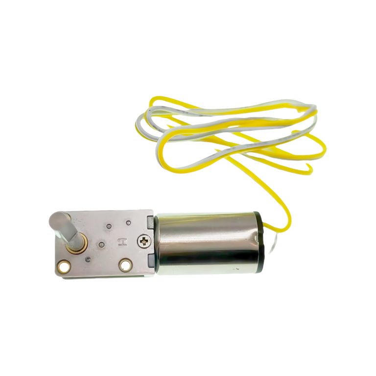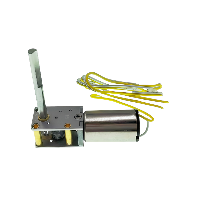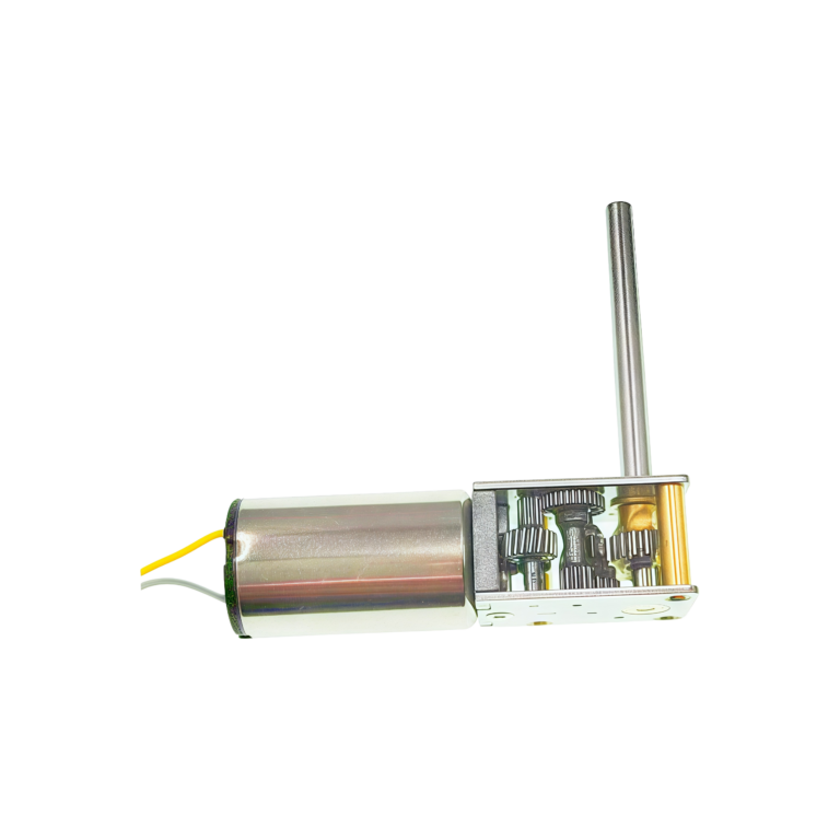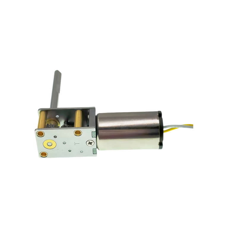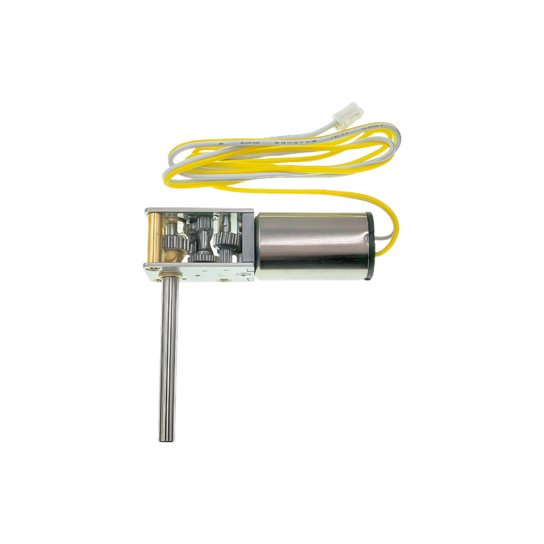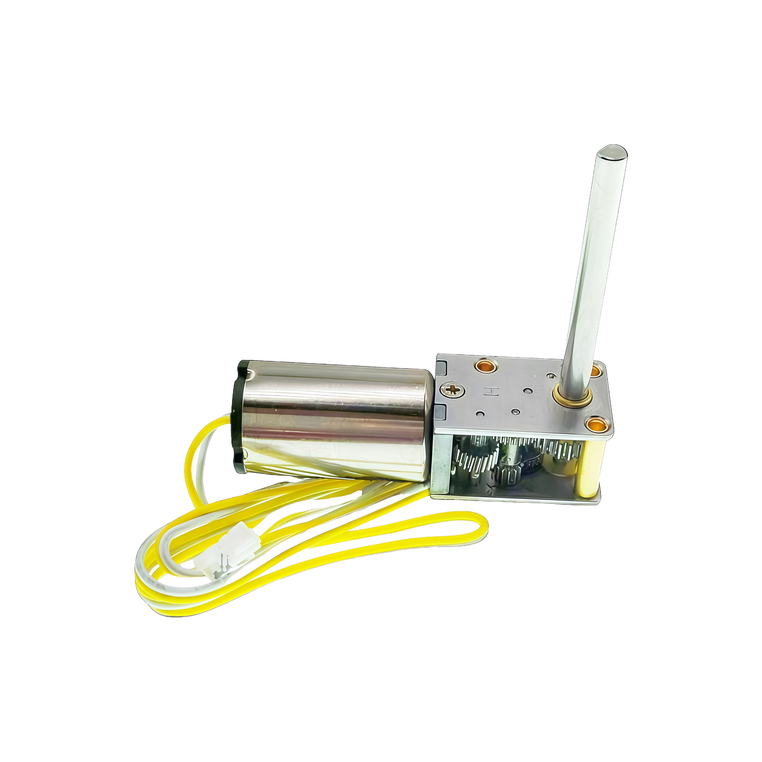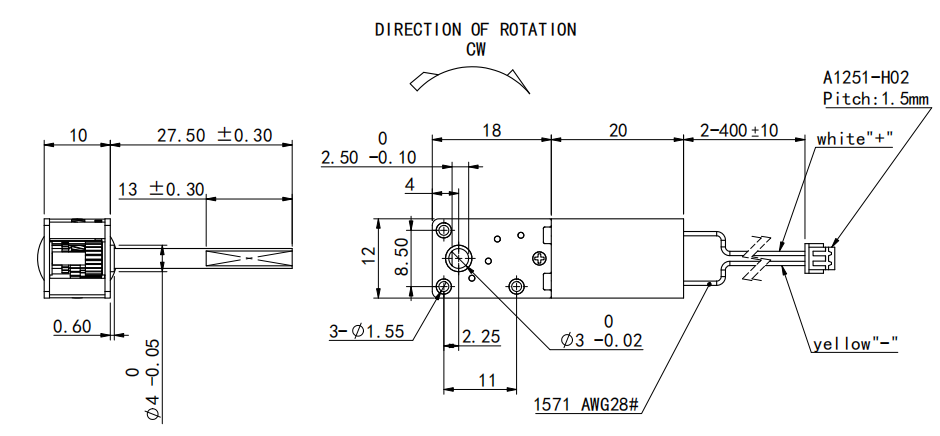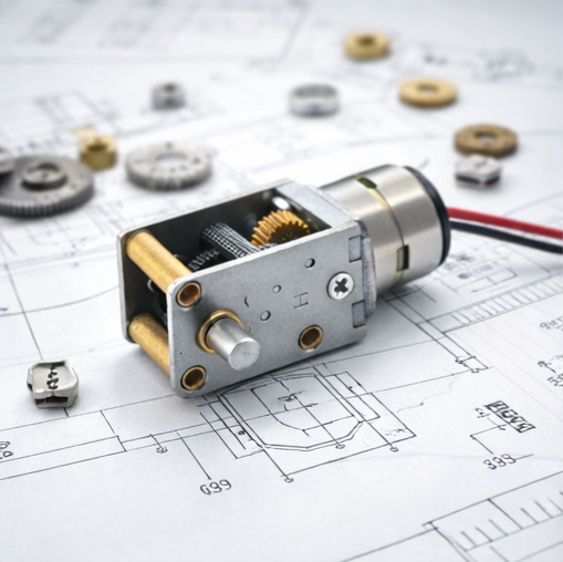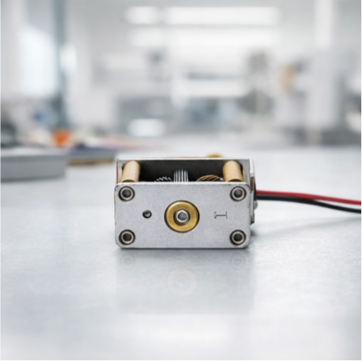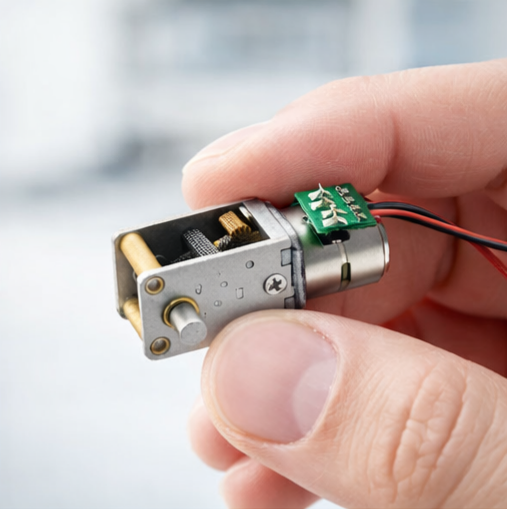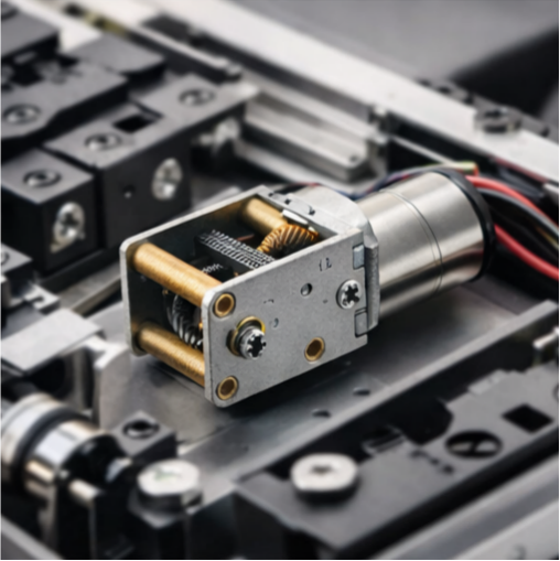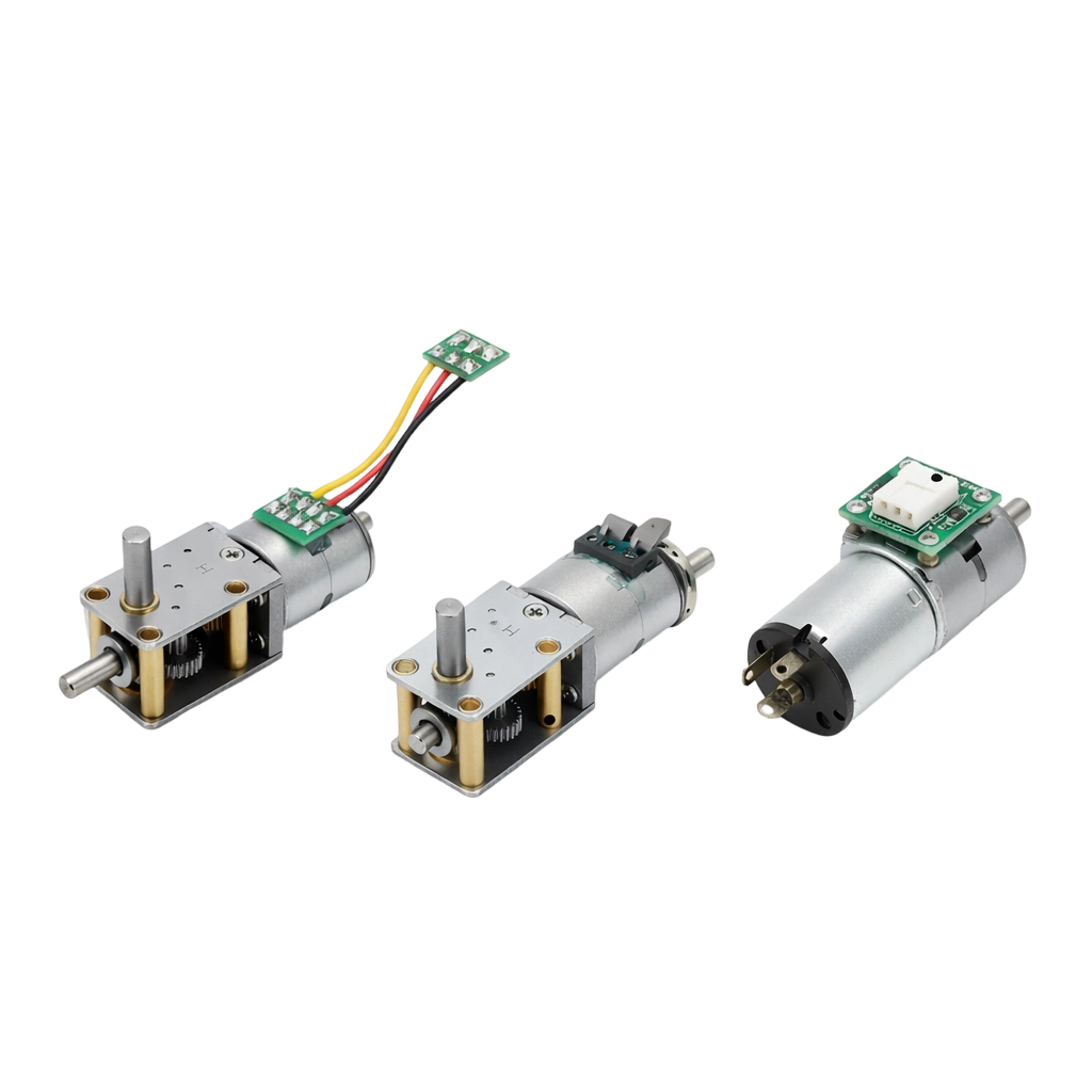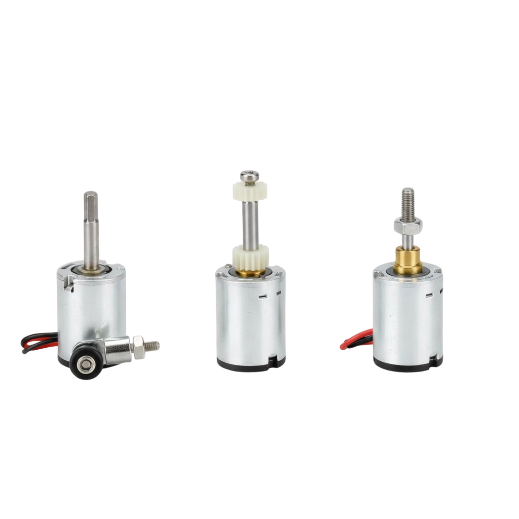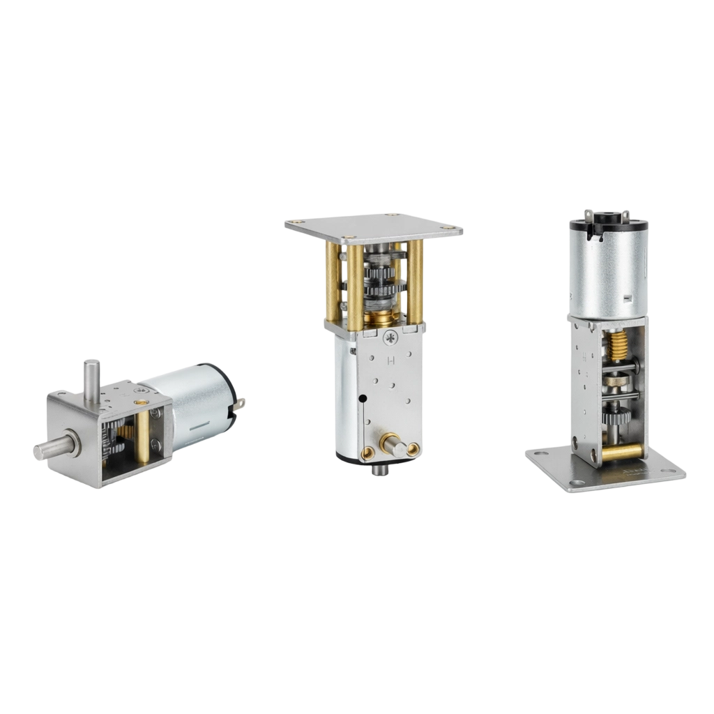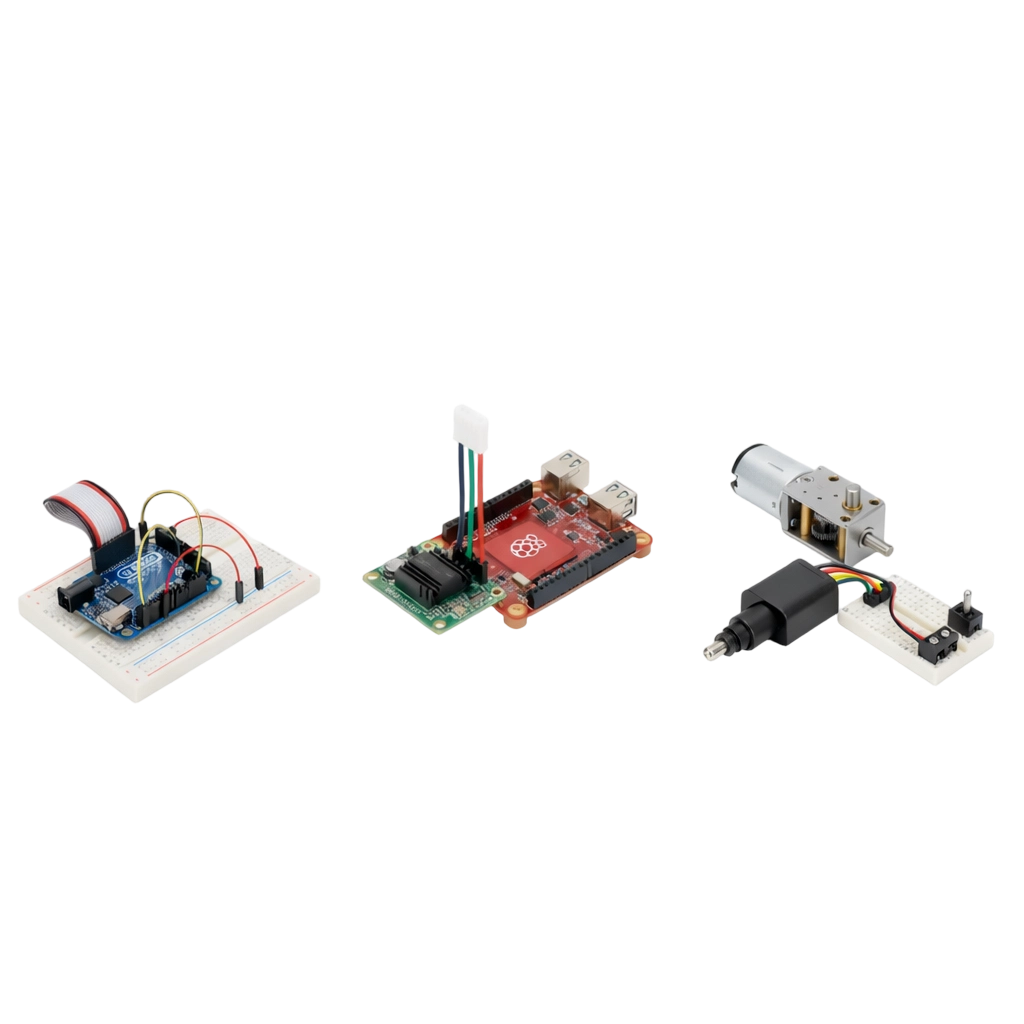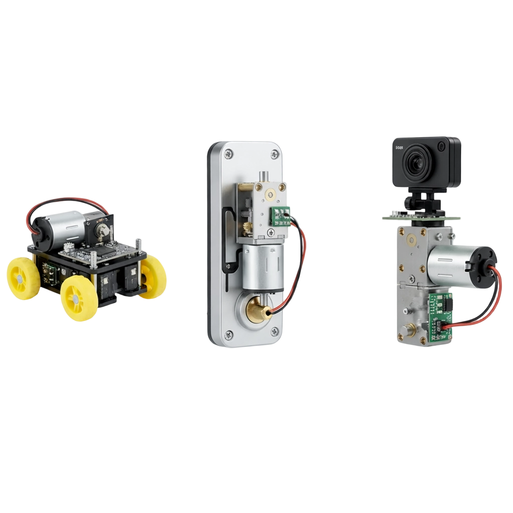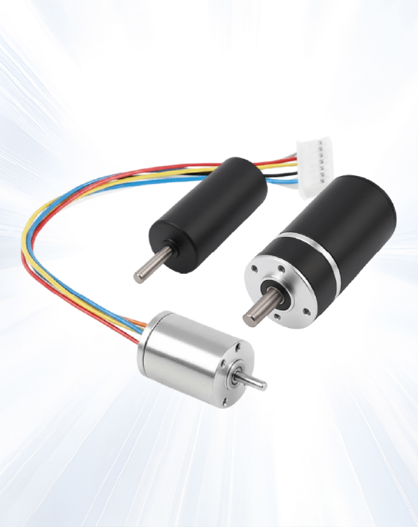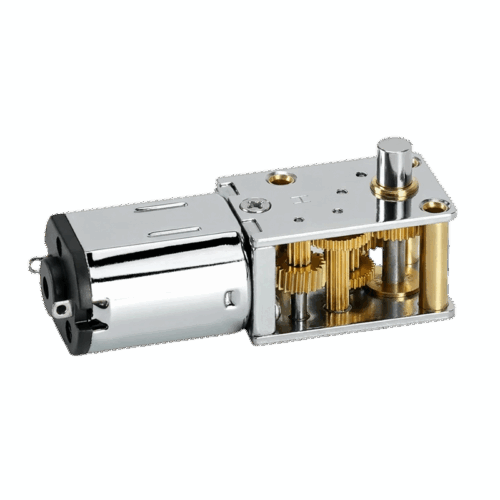
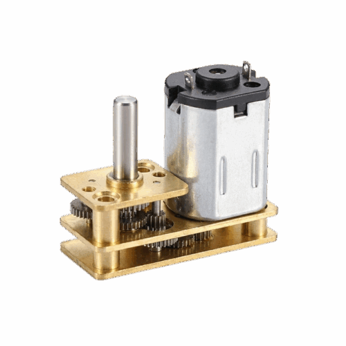
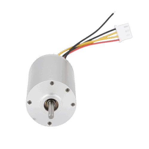
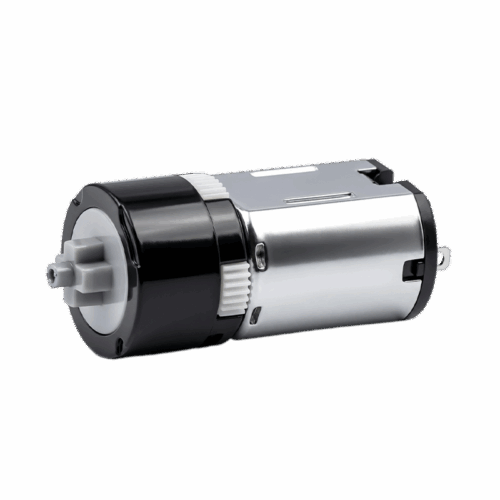


12mm Diameter 20 Micro Brushed Coreless Motor With 90 Degree Shaft Gearbox
This 12mm micro brushed coreless gear motor uses a 90-degree shaft gearbox for right-angle packaging in 3–12V systems, letting you route output sideways while keeping a defined 12V performance point for speed and torque planning.